1 Introduction <br> The car tachograph is a recording device used in automobiles. The device can record and store the vehicle's driving speed, mileage and other status information about the vehicle's travel and can output data through the interface. The wireless driving recorder combines the wireless communication method with the vehicle driving recorder to realize the function of the recorder and facilitate the user to read and process the data, which can solve the disadvantages of the traditional recorder to obtain data through the medium such as the U disk.
There are many ways to communicate wirelessly, among which the most widely used in industrial applications are ZigBee wireless communication, RF wireless communication and Wi-Fi wireless communication. ZigBee is mainly used to transmit low data rate communication with ultra low power loss. The main goal is to provide device control channels. RF is widely used in communications, automotive, medical, IT and other fields, with good security. The main goal is to provide equipment control channels, and the shortcomings are poor in anti-interference ability. Wi-Fi based modules are widely used in communications and control. The communication distance is long, the security is good, the networking is simple, the secondary development technology is mature, and the price is cheap. Therefore, when implementing the wireless telecommunication device wireless communication scheme, the Wi-Fi communication module is used to form a WLAN network to realize wireless communication of the recorder. The wireless drive recorder can be used in all types of vehicles, especially for enterprises and institutions, such as logistics companies with large fleets, stations, airports, and military logistics support.
2 system composition <br> The wireless tachograph system mainly includes wireless tachograph, receiving base station and recorder management software. The system composition is shown in Figure 1.
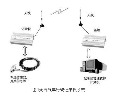
Among them, wireless tachograph mainly completes signal acquisition, data storage and data transmission. The main functions of the wireless tachograph are as follows:
1) Real-time recording of the following actions of the vehicle: left flashing light, right flashing light, reversing light, door state, high beam, low beam, brake light, car horn;
2) Measurement, recording, storage, recording and storage of suspected data;
3) Record related parameters of the vehicle (such as vehicle identification code, license plate number, driver code, driver's license number, real-time clock, motor vehicle driver's license number issued by the public security traffic management department, maximum speed of the vehicle);
4) transmitting the driving data of the vehicle by reading data or wirelessly transmitting through the U disk;
5) Driving time record, overspeed, fatigue driving alarm.
The main function of the receiving base station is to receive the data sent by the wireless tachograph and transmit it to the upper computer. The wireless tachograph can be configured to be used as a receiving base station. The functions are as follows:
1) Perform corresponding processing on the information transmitted by the recorder;
2) Send to the recorder management software computer through the serial port;
3) receiving the corresponding instruction of the host computer and forwarding it to the recorder;
4) Data wireless transmission function.
The recorder management software mainly completes the analysis of the data collected by the recorder, the data management function, and the configuration of the recorder function. The function is as follows:
1) Describe the entire driving process in real time, and play back the driver's entire driving process;
2) reading the original data recorded by the recorder;
3) Query the data in the database and statistically analyze the data uploaded by different recorders;
4) Perform chart processing on the obtained data to obtain a management reference.
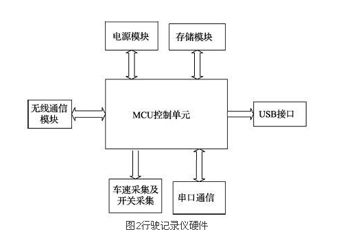
3 Wireless tachograph design and application 3.1 Wireless tachograph hardware design Wireless tachograph hardware mainly implements signal acquisition, data storage and wireless communication functions. The hardware circuit includes: MCU control unit design, power circuit design, vehicle speed signal and switch acquisition circuit design, data storage unit design, wireless communication module interface design, USB circuit design, etc. The hardware composition is shown in Figure 2.
3.1.1 MCU unit design The MCU of the wireless tachograph uses LPC 1766, which belongs to the LPC 1700 series Cortex-M3 microcontroller. The peripheral components of the microcontroller include up to 512 KB of flash memory, 64 KB of data memory, USB master/slave/OTG interface, 4 UARTs, 2 SSP controllers, SPI interface, 3 I2C interfaces, 2- Input and 2-output I2S interface, 8-channel 12-bit ADC, built-in clock, 4 general-purpose timers, 6-output general-purpose PWM, ultra-low-power RTC with independent battery, and up to 70 general-purpose I /O pin.
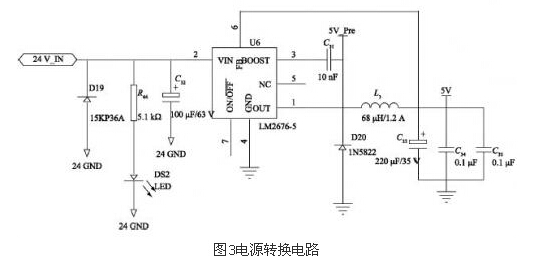
3.1.2 Power Circuit Design The main function of the power circuit is to convert the vehicle DC power supply 12 V or 24 V into 3 V (DC) and 5 V (DC) power supplies to provide power for each function module of the recorder.
A TVS diode protection circuit is added to the power input to suppress transient voltage spikes. The power supply converts the power to 5 V through the LM2676â€5 chip, and converts 5V to 3.3 V through the LM1117â€3.3 chip. The circuit is shown in Figure 3.
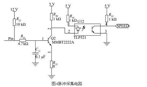
3.1.3 Vehicle speed signal acquisition The vehicle speed sensor is used to collect vehicle speed pulses. The vehicle characteristic coefficient is a parameter that is extremely important for the recorder to calculate the vehicle speed. It is related to the accuracy of vehicle speed and mileage data collection. After a lot of practice, a feasible method is summarized: the vehicle characteristic coefficient is the number of pulses output by the sensor every 1km of the vehicle, which is equal to the product of the odometer gear ratio and the number of pulses per revolution of the sensor, namely:
Characteristic coefficient = i6 (8)
Where: i: odometer speed ratio 6 (8): the speed sensor pulse number is 6 or 8.
For example, the Santana sedan odometer speed ratio is 975:1, and its sensor outputs 6 pulses per revolution. Its characteristic coefficient is 5850, which is 5860 pulses per kilometer. The pulse acquisition circuit is shown in Figure 4.
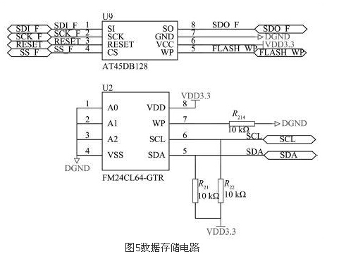
3.1.4 Data Storage Unit Hardware Design The wireless drive recorder data storage unit is composed of a combination of ferroelectric and Flash chips. During the running of the car, the recorder will store the collected data into the ferroelectric in seconds (user configurable) time interval, and divide the internal storage area of ​​the ferroelectric into 5 blocks: setting the parameter recording block and running the parameter recording block. , suspect point record block, fatigue record block, normal record storage block. After the data is full of ferroelectric, the data is moved to Flash.
The ferroelectric chip uses the FM24CL64 of RAM TRON, and is connected to the MCU through the I2C interface. The Flash chip uses ATM45's AT45DB128 and is connected to the MCU through the SPI interface. The interface circuit connection diagram is shown in Figure 5.
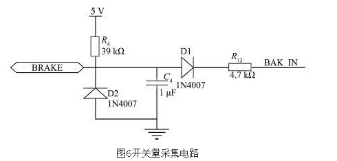
3.1.5 Switching Signal Acquisition Hardware Design The wireless driving recorder collects 8 switching signals and adopts a unified hardware interface circuit. For the effective level of the signal, it is divided by preparation. Take the brake circuit as an example to introduce the switch acquisition interface circuit as shown in Figure 6. .
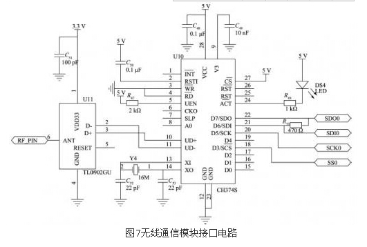
3.1.6 Wireless communication module hardware design For the reliability and security of wireless communication, the error correction mechanism of the wireless universal module adopts the retransmission mechanism. When the content of the data information to be sent is filled in the buffer to be sent, the module is sent. A CRC check will be added. If the receiver receives the wrong data frame, it will throw away no information, and the sender that did not receive the response will initiate the retransmission mechanism.
The wireless communication module selects the TL0902GU wireless communication module of CEC Huada Electronics Co., Ltd. The parameters of the wireless communication module are shown in Table 1.

The wireless communication module interface circuit is shown in Figure 7.
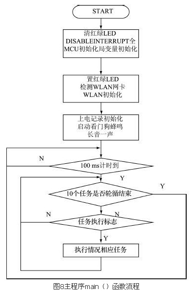
3.2 Recorder software design According to the function of the wireless tachograph software, the main function of the recorder software is divided into task flow of different timings, as shown in Table 2.
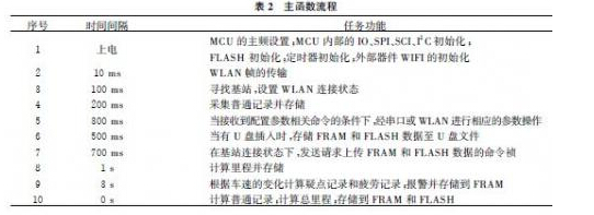
The software flow is shown in Figure 8.
3 Recorder Management Software Design <br> Wireless Travel Recorder Management Software is designed and developed using VC++6.0. The main function of the software is to complete the analysis of wireless tachograph data, recorder configuration, and data management. The software architecture is shown in Figure 9.
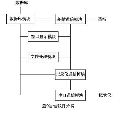
The management software uses the window display module as a human-computer interaction interface, calls the base station communication module, the file processing module, the recorder communication module, and the database module to implement base station communication, file processing, recorder communication, and database processing operations; file processing module, base station communication The module and the recorder communication module both call the database module to process the data; the recorder communication module forms a communication link and records for data interaction by calling the serial communication module and the recorder, and the base station communication module calls the network communication module and the base station to form a communication chain. Road, to achieve data interaction with the base station.
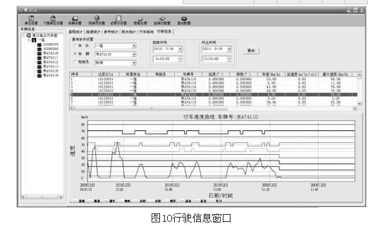
3.3.1 Management Software Main Interface The main window of the software interface is the main interface of the display of the mileage statistics window, showing the contents of the parking lot, the subordinate units and the license plate number. The mileage statistics window can query the mileage information of the vehicle through the contents of the fleet, the vehicle and the driver, and count the total mileage.
The driving curve window is used to display the driving curve of a vehicle with a certain license plate number for a certain period of time. The driving information is expressed in the form of a real-time curve to make the driving information more intuitive and readable, and also convenient for the user to view the speed situation and the switch information at a certain moment, as shown in FIG.
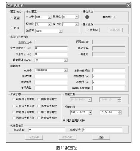
3.3.2 Configuration Interface When setting up the recorder, use the serial port setting tool to connect the recorder through the serial cable. The information that the user must configure includes: station ID, license plate number, vehicle characteristic coefficient, and initial mileage accumulation data. The configuration interface is shown in Figure 11.
Circuit Breaker Rocker Switches
Circuit Breaker Rocker Switches Gray,Circuit Breaker Rocker Switches Black,Circuit Breaker Rocker Switches Black White,Circuit Breaker Rocker Switches Blue
Yang Guang Auli Electronic Appliances Co., Ltd. , https://www.ygpowerstrips.com