 1 Introduction
In the system temperature measurement and control, the selection of temperature sensors is rapidly developing from analog to digital, and from integration to intelligence. MAX6625 is a new type of intelligent temperature sensor produced by Maxim in the United States. It is widely used in fan control, temperature warning, system temperature measurement and industrial equipment. MAX6625 integrates temperature sensor, 9-bit A/D converter, programmable temperature limit alarm and I2C bus serial interface in the same chip. MAX6625 contains 9-bit A/D converter. Can replace LM75. Built-in VPN engine to achieve.
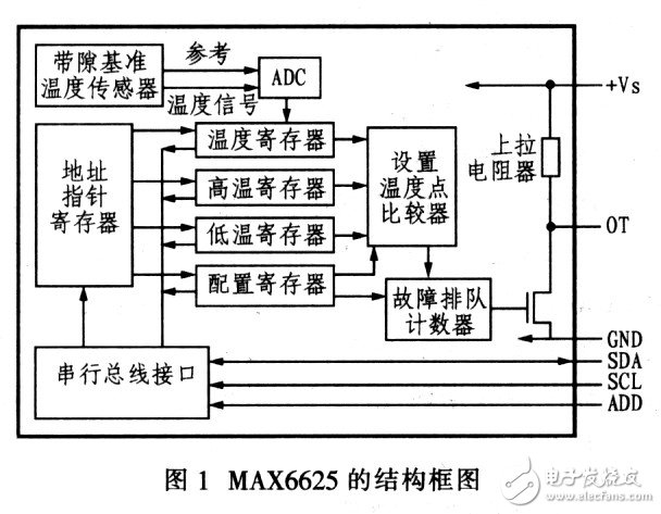
2 Structure and pin functionThe MAX6625 intelligent digital temperature sensor mainly includes bandgap reference voltage source and temperature sensor, A/D converter, 5 control registers (address pointer register, temperature data register, upper limit temperature register, lower limit temperature register and configuration register), setting temperature Point comparator, fault queuing counter and I2C serial bus interface circuit, etc. Its structural block diagram is shown as in Fig. 1.
MAX6625 adopts SOT23-6 miniaturized package. as shown in picture 2.
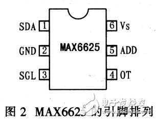
Its pin functions are as follows: SDA is a 12C compatible serial bidirectional data line; SCL is a 12C compatible serial clock line; ADD is: I2C compatible address setting terminal; 0T is temperature alarm output terminal; Vs is power supply; GND is Power ground.
3 The working principle of MAX6225MAX6625 is programmed by the main controller through the FC bus interface. Set the alarm mode and polarity of the OT end, temperature alarm point, and read the measured temperature data. MAX6625 is a slave device that supports byte and word read and write operation commands of the I2C bus. A 12C bus can be connected to 4 MAX6625. It can realize one-point and multi-point temperature measurement and control.
3.1 Address selection
The MAX6625 uses the ADD pin to set the address. When the ADD terminal is connected to any one of the GND, Vs, SDA, and SCL pins, it represents an independent address, which is 1001000B, 1001001B, 1001010B, 100101lB, respectively. When the host controller accesses the MAX6625, it first sends the address to the 12C bus.
3.2 The initial setting of MAX6625
Before starting normal work, you should first set the working mode and polarity of the MAX6625OT alarm terminal, and the high temperature and low temperature points of the alarm. The realization of these functions is completed by the main controller by writing specific data to the relevant registers within the MAX6625 through the 12C bus. The following introduces the 5 registers, OT alarm operating mode and polarity determination within the MAX6625, and the writing process of the register data.
3. 2. The control register of 1 MAX6625
(1) Address pointer register
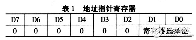
The main controller passes. The I2C bus writes data to the address pointer register. Make sure that one of the other 4 registers is selected. The data format of the address pointer register and the selection of other registers are shown in Table 1. When D1, D0=00, select the temperature register; when D1, D0=01. Select the configuration register; when D1, DO=10, select the low temperature register; when D1, DO=11, select the high temperature register.
(2) Temperature register
The length of the MAX6625 temperature register is 16 bits. Store the latest temperature conversion data, D15 is the sign bit. D14~D7 are valid data. D6~DO bits are 0. The data in the temperature register is the complement of Celsius temperature. 1LSB means 0.5°C.
(3) High temperature and low temperature registers
MAX6625 high temperature, low temperature register length is 16 bits, of which 9 bits of valid data. Fill the unused bits with 0. The data format is the same as the temperature register.
(4) Configuration register
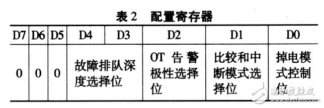
The configuration register is an 8-bit read/write register, and its data format and function are shown in Table 2. The D7, D6, and D5 digits are 000. The D4 and D3 bits are the fault queuing depth setting bits. When D4, D3=00, the fault queuing depth is 1: When D4, D3=01, the fault queuing depth is 2: When D4, D3=10. The fault queue depth is 4; when D4, D3=11. The fault queue depth is 6. D2 is the OT alarm polarity selection bit. When D2=0, the low level is effective; when D2=1, the high level is effective. D1 is the comparison and interrupt mode selection bit. When D1=0, it is the comparison mode; when DI=I, it is the interrupt mode. DO is the power-down mode control bit. When D0=0, it is normal operation; when D0=I, it is power-down mode.
3.2.2 OT alarm mode and polarity
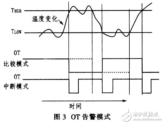
The D1 data bit in the configuration register is used to set the alarm mode of the OT end. When Dl=0, it is the comparison mode; when D1=1, it is the interrupt mode. In the comparison mode, when the number of consecutive conversions exceeding the value (THIGH) in the high temperature register is equal to the fault queue depth. OT alarm. When the number of consecutive conversions lower than the value (TLOW) in the low temperature register is equal to the fault queue value, the OT alarm is cleared. For example: THIGH is set to +100°C, its TLOW is set to +80°C, and the fault queuing depth is set to 4. OT will not alarm until 4 consecutive conversions exceed +100°C. When 4 consecutive conversions are lower than +80℃, OT will exit the alarm. In interrupt mode, the MAX6625's high temperature or low temperature alarm is based on the previous temperature alarm. There are low temperature alarms and high temperature alarms on the OT end, and it is determined that the 0T end alarm depends on a certain condition. Suppose that the fault alarm is cleared after power-on, and a high temperature point alarm occurs on the MAX6625. After the high temperature warning, a low temperature warning appeared on the MAX6625. After the low temperature alarm, a high temperature alarm appears on the MAX6625. The high temperature point or low temperature point alarm alternates at a certain tempo. Once any fault occurs, the alarm it activates is indeterminate, and cannot be determined until after the operation of reading the temperature register. Then correspond to each fault alarm. Similarly, the activation of any alarm is conditional on the depth of the fault queue. Figure 3 shows a schematic diagram of two alarm modes at the OT end when the alarm polarity is low. When OT alarms, in order to prevent false alarms caused by interference. The MAX6625 has a fault queuing depth counter inside, and the alarm is triggered when the continuous number of high temperature or low temperature alarms is equal to the programmed fault queuing depth number. The fault depth in Figure 3 is 4.
3.2.3 Write configuration register, high temperature register and low temperature register
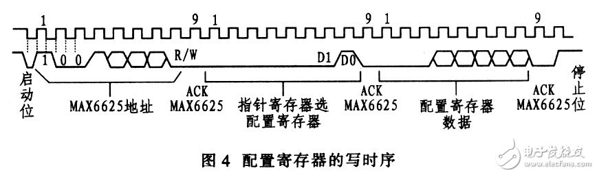
The process of the main controller writing data to the MAX6625 configuration register is to write the MAX6625 address first, and then write the configuration register address to the pointer register. Then write the configuration register data, the sequence is shown in Figure 4. The write timing of high and low temperature registers is basically the same as that of configuration registers. But note that the high and low temperature registers are in 16-bit data format.
3.3 Read the temperature register
In simple temperature control, only the initial setting is required. In temperature measurement and display applications, it is necessary to read the current value of the MAX6625 temperature register. The reading process is to first select the MAX6625 to be read, and then select the register to be read. When reading the register data, rewrite the address of the MAX6625, but the R/W bit should be 1.
4 Application and programming of MAX6625MAX6625 can be used in fan control, temperature warning, system temperature control and industrial equipment. Here are examples of distributed temperature monitoring and display applications. Only the connection circuit between the single-chip microcomputer and 4 MAX6625 is given. As shown in Figure 5. In the application programming, should first set up MAX6625 with the one-chip computer according to the system requirement, and then read the value of the temperature register in MAX6625.
4.1 The setup program of MAX6625
In distributed multi-point temperature measurement or monitoring applications, the initial settings of the MAX6625 include the selection of MAX6625, the data writing of configuration registers, and the writing of high and low temperature registers. Take device 1 as an example for programming. Because AT89C51 has no dedicated 12C bus interface. Therefore, the analog 12C interface is used for programming here.
(1) Write program of configuration register
WRITE: LCALL START: Generate start bit
MOV A. #10010000B; MAX6625 device 1
address. Rï¼W=O
LCALL WRBYT: write device address
LCALL CACK: Query MAX6625 response
JB FO, WRITE; restart without response
MOV A, #00000001B; there is an answer
LcALL WRBYT: write configuration register address
LCALL CACK
JB F0, WRITE
MOV A, #00010000B: Write configuration register data
LCALL WRBYT
LCALL CACK
JB FO, WRITE
LCALL STOP; generate stop bit
RET
(2) Writing procedures for high and low temperature registers
WRWEl: LCALL STAlit; Generate start bit
MOV A. #10010000B; MAX6625 device l
Write the address, R/W=O
LCALL WRBYT: write device address
LCALL CACK: Query MAX6625 response
JB F0, WRITEl; restart without response
MOV A. #00000011B; There is an answer
LCALL WRBYT: write high temperature register address
LCALL CACK
JB F0, WRITEl
MOV A, #01010000B; write high temperature register high
8-bit
LCALL WRBYT
ICALL CACK
JB FO, WRITEl
MOV A, #00OO000B: Write low 8 bits of high temperature register
LCALL WRBYT
LCALL CACK
JB F0, WRITEl
LCALL STOP
RET
The programming setting of the low temperature register only needs to change the address and data.
4.2 Register read program of MAX6625
The register reading program of MAX6625 includes temperature register reading, high and low temperature register reading and configuration register reading. The read procedure of the temperature register is as follows:
READ: LCALL sTART
MOV A. #10010000B
IJCALL WRBYT: Write and read the address of MAX6625
LCALL CACK
JB F0, READ
MOV A. #0000000B
LCALL WRBYT: write the address of the temperature register
LCALL CACK
JB F0, READ
LCALL START
MOV A, #10010001B; R, W=1
LCALL WRBYT: Write and read the address of MAX6625
LCALL CACK
JB F0, READ
LCALL RDBYT: Read temperature register high 8
LcALL MACK: The main controller answers
LCALL RDBYT: Read the lower 8 bits of the temperature register
LCALL MNACK: The main controller does not answer
LCALL STOP
RET
Due to space limitations. Related subroutines are omitted. The MAX6625 intelligent digital temperature sensor can cooperate with various emblem controllers to form an intelligent temperature control system. It can also work independently from the microcontroller. It constitutes a temperature controller.
Our company specializes in the production and sales of all kinds of terminals, copper terminals, nose wire ears, cold pressed terminals, copper joints, but also according to customer requirements for customization and production, our raw materials are produced and sold by ourselves, we have their own raw materials processing plant, high purity T2 copper, quality and quantity, come to me to order it!
Copper Connecting Terminals,Cable Lugs Insulated Cord End Terminals,Pvc Insulated Cord End Terminal,Cable Connector Insulated Cord End Terminal
Taixing Longyi Terminals Co.,Ltd. , https://www.longyicopperlugs.com