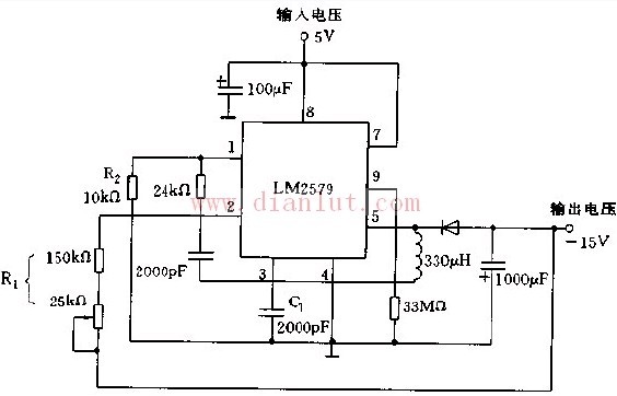
DC/DC converter
The BOOST DC/DC converter is also known as a boost chopper or boost converter. The principle of the DC/DC converter is to convert the input DC power into AC power through a self-excited oscillation circuit, then convert the voltage into a DC output through a transformer, or convert the AC circuit into a high-voltage DC output through a voltage doubler rectifier circuit.
When the control signal Ui is at a high level, the switch Q is turned on, the energy flows in from the input power source, and is stored in the inductor L. Since the saturation voltage drop is small when the Q is turned on, the diode D is turned off and is turned off. The energy in the filter capacitor C is released to the load. When the control signal Ui is low, the switching transistor VT is turned off. Since the current in the inductor L cannot be abruptly changed, the induced potential generated by it will prevent the current from decreasing, and the polarity of the induced potential is left negative and right positive, so that the diode D Turned on, at this time, the energy stored in the inductor L charges the filter capacitor C through the diode D and is supplied to the load.
Circuit design: The main components to be determined are output filter capacitor C, inductor L, switch VT and diode D.

2 Bay Fm Dipole Antenna,External Fm Dipole Antenna,2 Bay Dipole Antenna For Professional,Fm Dipole Antenna Calculator
Anshan Yuexing Technology Electronics Co., LTD , https://www.yxhtfmtv.com