0 Preface
In remote areas far from the power grid, solar power generation uses photovoltaic controllers, battery packs, and photovoltaic panels to form independent photovoltaic power plants, of which photovoltaic controllers are the core of the entire power station. The topology of the PV controller usually has two types: DC/DC type and straight-through type. The DC/DC type can be subdivided into MPPT type and resonant type, but the DC/DC type controller has large inductive components. The existence, in the case of high current applications, its volume, weight and heat will increase sharply, limiting its practical application in the field of high power; while the through-type controller is relatively advantageous in the field of high power, even if the photovoltaic current reaches several hundred Ampere, its volume, weight and heat are not too large, so the straight-through controller has been widely used in high-power fields such as mobile communication base stations and border guard posts. However, the through-type controller still has some defects, and its advantages and disadvantages are analyzed below.
1 Insufficient existing control methods
The existing through-type photovoltaic controller generally adopts a class 3 charge and discharge control mode for charging and discharging the battery.
(1) Step-by-step input system, which divides the photovoltaic cells into N independent photovoltaic sub-arrays, defining N battery voltage control points Vi (i = 1, 2, ... N; Vi "Vi + 1), when the battery voltage is greater than In Vi, the ith photovoltaic sub-array is turned off, and vice versa. Thus, as the battery voltage increases, the charging current stepwise decreases step by step; otherwise, it increases step by step. Advantages: This charging control method basically satisfies the charging needs of the battery, the control logic is simple and easy to implement, and the switching energy loss of the electronic power switching device is small; disadvantages: the control precision is not high, the voltage fluctuation range is large, and some advanced automatic control The algorithm cannot be implemented.
(2) On this basis, an improved control method with time factor is added, and the battery voltage control point is set to 1 control point Vs. When the battery voltage is greater than Vs, the ith photovoltaic sub-array is turned off, and the delay is 1 After a fixed time, if the battery voltage is still greater than Vs, then the i+1th photovoltaic sub-array is turned off, and so on, until the Nth photovoltaic sub-array is turned off; otherwise, the conduction is turned on, and the conduction process also has the above delay. Advantages: This charging control method reduces the variation range of the battery voltage and has the advantages of the former charging control method. Disadvantages: easy to cause the controller to oscillate, especially the selection of the delay time, with the solar battery and battery capacity. Changes with the configuration of the load, otherwise it will lead to loss of control, in severe cases, the battery will be overcharged or over-discharged and scrapped.
(3) Pulse width modulation system (full control type PWM control mode), that is, photovoltaic cells are not molecular arrays, all photovoltaic sub-arrays are connected in parallel to form one total photovoltaic cell array, and then all-power electronic switches are used for all-pass Fully-breaking PWM control, this method can accurately control the battery voltage at 1 voltage point. Advantages: high voltage control accuracy, can adopt various advanced automatic control algorithms; Disadvantages: Power switching of power electronic switching devices is large, under the same voltage level, the current level of power electronic switching devices is very high, The device is demanding, and for high-power photovoltaic controllers, the heat sink is bulky.
2 fine coarse adjustment combination PWM new control scheme
Aiming at the shortcomings of the above three schemes, this paper proposes a new control scheme for fine coarse tuning combined PWM control. The photovoltaic cell is still divided into N independent photovoltaic sub-arrays of the same configuration (i = 1, 2, ... N), but only the first photovoltaic sub-array (i = 1) is PWM controlled, and the remaining photovoltaic sub-arrays (i =2,3,...N) still adopts ordinary switch control, the control mode is: assuming that the total photovoltaic current when all the N sub-arrays are turned on is I, the photovoltaic current when each photovoltaic sub-array is turned on separately is I/N, if the PWM control duty cycle of the first PV sub-array varies from 0 to K, the PWM current of the first PV sub-array can be accurately controlled to (j/K) & TImes; (I/N) , where j=0~K changes; if the PWM precise control of the first photovoltaic sub-array is matched with the coarse control of the remaining N-1 photovoltaic sub-arrays, the current variation range is between 0 and I. Any precise current output, the value is: (j / K + m) & TImes; (I / N), where m is the number of conduction of the remaining N-1 photovoltaic sub-array, m = 0 ~ N-1 ( m=0, indicating that the remaining N-1 photovoltaic sub-arrays are all turned off); the controller only needs to select the size of m(0~N-1) and j(0~K) to control the fine Photovoltaic output current, the current resolution accuracy of I / (KN), the PWM duty cycle corresponding to the variation range of the third category of full-controlled PWM control mode is 0 to control the effect of KN.
3 Realization of fine and coarse tuning combined PWM control
The microprocessor of this controller uses the C8051F020 microcontroller, as shown in Figure 1.
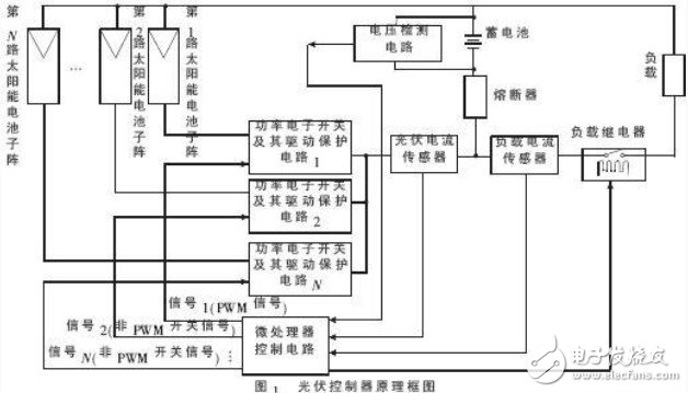
Through the external two current sensors and the voltage detection circuit, the parameters such as the photovoltaic current, the load current and the battery voltage are obtained through the internal AD conversion of the microprocessor. The microprocessor simultaneously issues N switch control signals, wherein the first signal is generated by a PWM control unit inside the microprocessor, and the second to N signals are generated by a common digital I/O port (non-PWM) inside the microprocessor. . When the i-th power electronic device is controlled to be turned on, the i-th photovoltaic sub-array charges the battery and supplies power to the load. The principle of charging control of the battery is to perform different constant-voltage charging at different time periods. The charging process is divided into four processes: strong charging, equalizing, absorbing and floating charging. In addition to strong charging, the three stages of equalizing, absorbing and floating charging are constant voltage control. For the constant voltage control of the battery, various intelligences can be used. The control algorithm, the controller specifically adopts the PI (proportional integral) adjustment algorithm, and is combined with the fine coarse tuning combined PWM control method.
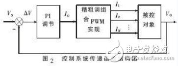
Control system transfer function structure shown in Figure 2, VS is the battery voltage setting value, VO is the battery voltage actual output value, the difference between the two â–³V input PI regulator, get the desired output current IO, fine adjustment of IO Combined PWM implementation, the implementation of the flow chart shown in Figure 3.
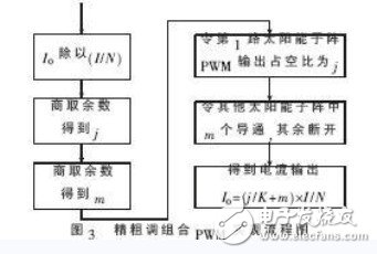
That is, divide IO by (I/N), take the remainder to get j, take the integer to get m. Then let the PWM duty cycle of the first photovoltaic sub-array be j, so that m of the remaining photovoltaic sub-arrays are turned on. The remaining PV sub-array is broken, resulting in an accurate IO output: IO = (j / K + m) & TImes; (I / N). This current is supplied to the battery and the load, and the battery output voltage VO is maintained at a constant voltage by the PI algorithm. In a control system consisting of 6-channel photovoltaic sub-array, the PWM voltage, current and total photovoltaic current waveform of the first photovoltaic sub-array are shown in Fig. 4.
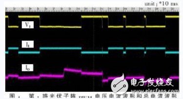
The voltage here refers to the voltage across the power electronic switch, and in a relative time, the voltage and current of the second to sixth photovoltaic sub-array changes very little (unless the coarse adjustment has an action), otherwise it is a straight line.
4 Conclusion
In this solution, only one PV sub-array adopts PWM control, and the remaining PV sub-arrays still adopt ordinary switching control. Compared with the total PWM control after all PV arrays are connected in parallel, this fine coarse-tuning combination realizes PWM precise control. The PWM switch energy loss is reduced by (N-1)/N (N is the number of photovoltaic sub-arrays), which reduces the heat sink volume; since multiple independent photovoltaic sub-arrays are still used for control, at the same voltage level, The power switching device has a low current level requirement, and a low-cost power switching device can be used in parallel to realize one sub-array, which reduces the cost, and at the same time has a high-precision current output for PWM control of all photovoltaic arrays, and is regulated by a test system. The output complies with national standards. Due to the small current involved in PWM chopping and good electromagnetic compatibility, it has passed the EMC test and obtained CE certification. It has been put into practical use in a series of photovoltaic controllers with a nominal voltage of -48 V and a current range of 30 A to 400 A. Operational practice shows that this solution has fully achieved the expected design effect.
Heated Grip Elements can be used in many field.Sush as handgrips heater for snowblower.motocycle and all-terrain vehicle.With the high heat conversion rate of heating elements,our handgrip heater can rise the temperature within few minutes and keep your hand warm.Not only did we supply manufactured handgrip heater product but also offer service of custom-made heated grip .We look forward to build business cooperation with customers worldwide.
Heated Grip Elements
Handgrip Heating Film,Motocycle Handgrip Heater,Snowblower Heated Grip,Heated Grip Elements
ShenZhen XingHongChang Electric CO., LTD. , https://www.xhc-heater.com