This article mainly analyzes several sound card microphone power amplifier circuits, and hopes to help you learn.
The super simple sound card microphone amplifier is used for the computer sound card to be amplified in the front end of the collective microphone. The reason for the production is that the sensitivity of the sound card microphone is too low, and the speech is very difficult. After debugging, the sound of the lighter is clear from the microphone 3 meters, and the effect is good.
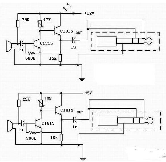
The triode is any low-frequency small power tube, such as C1815, C945, and 9014. Frequency, beta, power is too high, but it is not good. The input and output capacitor values ​​are not recommended to be too large. For voice purposes, the values ​​in the figure are sufficient.
The 75k resistor is responsible for the microphone bias voltage. The high internal resistance multimeter is used to measure the microphone positive and should be 0.2~1V. Otherwise adjust. The voltage is high, the gain is large, and the noise is large. vice versa.
The 680K resistor determines the operating point and feedback. It can be used up to 1M from 500K, with large gain and large distortion. Small is the opposite.
The 47K variable determines the working point of the triode. For different tube types, the supply voltage needs to be changed accordingly, and the front and rear stages are implicated. Adjust to minimize distortion and maximize gain.
The voltage can be 5~15V. Of course, the work point should be adjusted accordingly. High voltage, low distortion and high gain. The power supply should not be taken from the 5V~12V output of the computer power supply box. There is interference from the host square wave, and the external independent power supply is used. Even cell phone chargers are available.
The light-emitting diodes are protected; for work instructions, it is best not to save them.
The shell can be used with a common serial box, the circuit is too simple, and it is directly lap welding. Note that the ground wire does not form a loop to avoid interference and self-excitation.
After commissioning, consider the mechanical strength problem. The space inside the serial box can be filled with sealed silicone.
The connector is directly bonded to the half of the serial box with epoxy resin (two-component adhesive). Note that the glue is less, and it is added to several key points. Too much, it is troublesome to stick the movable contact.
The sensitivity of the dynamic microphone is too low, so the amplifier is too strong, try to use the op amp when you are mental. If you want to use 1.5V power supply, you can remove the LED, recalculate the next few bias resistors, ensure that the transistor b, e 0.6V, microphone bias 1V, gain and distortion. Personally think that the 5V solution is more convenient, the distortion and gain are more compromised, the used chargers are all over the place, there is electricity to grab one, and the emergency can also hang USB to take power.
Unexpected discovery:
1, originally thought that the sound card microphone input is mono. This time, I found out that a new sound card chip supports dual-channel mic. I already knew that I would choose a large parallel box to do stereo telephony.
TDA2822 makes microphone power amplifier circuit This circuit has few external components, simple production, and the sound quality is unexpectedly good. A two-channel audio amplifier integrated circuit is used. Its main features are high efficiency, power consumption, typical static operating current is only about 6mA, the integrated circuit's voltage adaptability (1.8V ~ 15V DC), even at 1.8V low voltage, there will still be about 100mW The power output, the specific circuit is as shown.

The electret microphone MIC converts the picked-up sound signal into an electrical signal, and then introduces it from the 2 pin of U1 via C2 and W, and then pushes the speaker to pronounce after being amplified by U1 audio. This machine is connected to the BTL output circuit, which is good for improving the sound quality and reducing the distortion. At the same time, the output power is also increased by 4 times. When the power is supplied at 3V, the output power is 350mW.
Resistors R1 and R2 are all selected from 1/4W metal film resistors. W is a small carbon film potentiometer. C2 is best to use monolithic capacitors. If no good quality ceramic capacitors should be used, C1, C4 and C3 should be made of high quality 16V. Electrolytic capacitor with low leakage current, MIC uses high sensitivity electret microphone. K uses a small push button switch or toggle switch, U1 selects TDA2822M or TDA2822, can also be replaced by D2822. According to the numerical values ​​in Figure 1, it usually works without debugging.
Electret microphone detection:
For example, use the RX 1O0 file of the MF47 multimeter to measure the Great Wall CZIII electret microphone. When the black pen is connected to the electret microphone core wire and the shell, the multimeter pointer refers to 3kΩ. When the air is blown, the pointer refers to the value of 4kΩ (also The microphone resistance becomes smaller). If you blow hard, the multimeter pointer swings very small. You can reverse the two test leads. If the multimeter's hands still swing very small, the electret microphone is damaged.
In the application of the electret microphone, the drain D must be connected to the positive pole of the power supply through a 4.7~10kΩ resistor, and then connected to the amplifier circuit as shown.
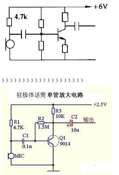
Adding an amplifier to the microphone
The electronic components are as follows: resistor R1 is 1 kΩ, resistor R2 is 1 MΩ, and R3 is also 1 kΩ. The triode vT is 9014, the capacitor c1 is 4.7uf, the c2 is 4.7uf, and the battery 1st section 5 is enough.
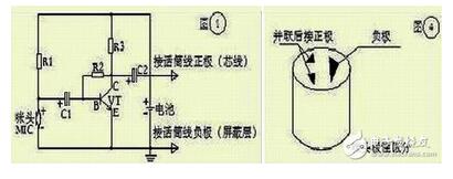
First, the working principle of the amplifying circuit Figure 1 is the circuit diagram of the entire microphone amplifying circuit, as can be seen from Figure 1, the whole circuit only needs six or seven originals. The following is a general description of the working principle, in which the resistor R1 is responsible for supplying the working voltage to the microphone, R2 and R3 are responsible for providing the bias voltage to the triode, and the capacitor C1 is responsible for coupling the signal of the microphone to the triode for amplification, and finally the amplified signal passes through the capacitor. After C2 is coupled, it is sent back to the positive pole of the microphone line, that is, the outermost layer of the microphone line (that is, the outer layer of copper). Figure 2 shows the materials or electronic components we use in our production.
Second, the production of the following considerations The specifications of the electronic components required for the entire amplifier circuit are as follows: resistor R1 is 1KΩ, resistor R2 is 1MΩ, resistor R3 is 1KΩ, transistor VT is 9014, capacitor C1 is 4.7μF, capacitor C2 is 4.7μF The battery can be used as a general fifth battery. Generally, it can be used for about half a year. The finished circuit board after the completion of the production is shown in Figure 3.
Pay attention to the following points during the production process:
1. The pins of the triode must be connected, otherwise they will not be amplified. The pins are divided into the following triode leads downwards, the flat side faces themselves, followed by E (emitter), B (base) and C. (collector); 2. The microphone microphone is also polar (see Figure 4 for details);
3. The polarity of the coupling capacitor can be distinguished by the mark. The pin with the arrow and marked "-" is the negative pole, and the positive pole is generally not marked.
Since the components are small, they can be directly soldered to the shed. After the circuit board is completed, it can be directly loaded into the base of the microphone. The power lead of the circuit board can be connected to the battery slot reserved by the microphone.
Third, the effect test After trial use, the effective distance of the microphone can reach 5~6 meters, and the voice input function of Office Word 2003 is also very obvious. It can be accurately recognized by speaking about 1 meter from the microphone.
This kind of brush is metal brush. Metal brush is made up of ordinary metal brush and metal brush with small wheel. Metal brushes will increase of service life,so it will save your money. Every metal brush has two lines of preventing ESD. They can effectively eliminate ESD and also can eliminate a large number of mites. Metal brush is also a dual purpose brush. It not only can clean the wooden Floor,but also the carpet. So it will let your homework easily. Now please see the pictures about metal brush.


Metal Brush , Static-Free Brush, Big Suction Brush
Ningbo ChinaClean Household Appliances Manufacture Co., Ltd. , https://www.chinaclean-elec.com