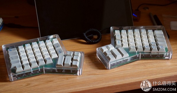
Familiar with the mechanical keyboard or ergonomic keyboard, heard ErgoDox should be a lot, ErgoDox is an open source split ergonomic mechanical keyboard. The ErgoDone to be said today is an improved, cost-reduced project based on the open source ErgoDox.
Compared to ErgoDox, ErgoDone's main hardware changes are as follows:
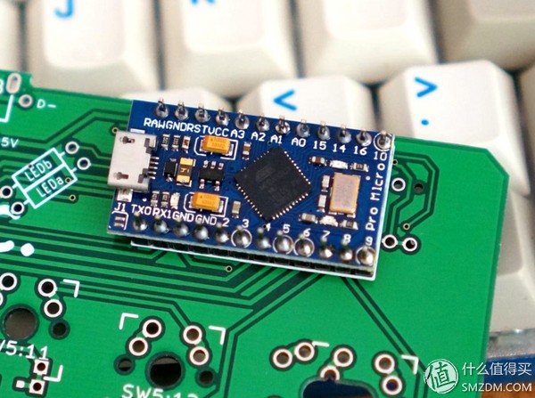
1. The main control changed from Teensy 2.0 to Pro Micro, which saved about 60 yuan in cost.
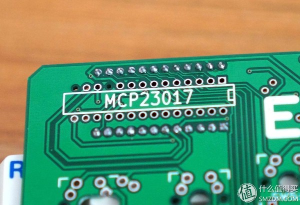
2. The IO expansion chip was changed from MCP23018 to MCP23017, which saves about 10 dollars.
3. In order to facilitate the use of some users as a one-handed keyboard, the main hand is changed from the right hand to the left hand, and the left hand can be used alone.
4. The LED light is changed from the axis light to the upper right corner of the left hand and placed vertically. It is more intuitive.
The other is the change of the trace, and the optimization of the firmware function, these will be followed later.
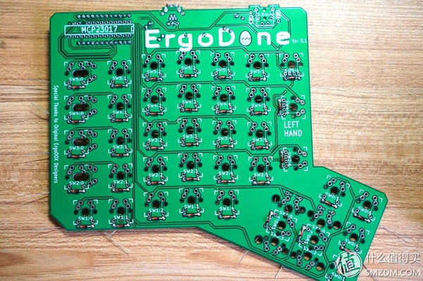
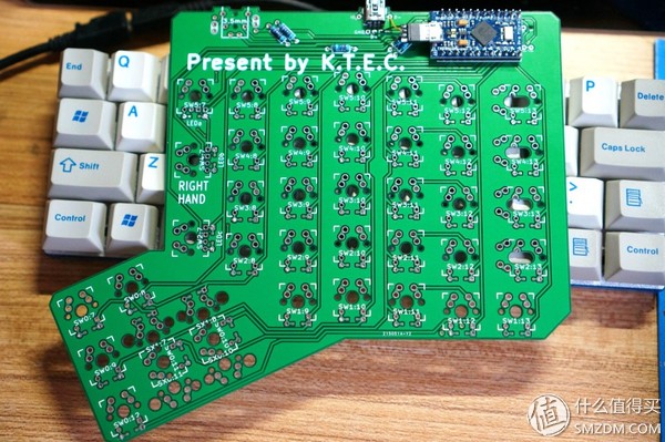
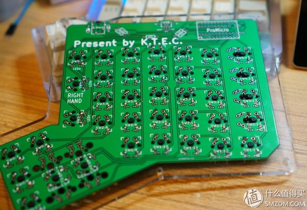
Hand items are as follows. The following is the earliest version of the project, the difference is whether this version of the main hand or the right hand. This includes a set of acrylic shells (the sticker on the acrylic shell has not been torn off), two PCBs (one for the left hand and one for the right hand), and several parts.
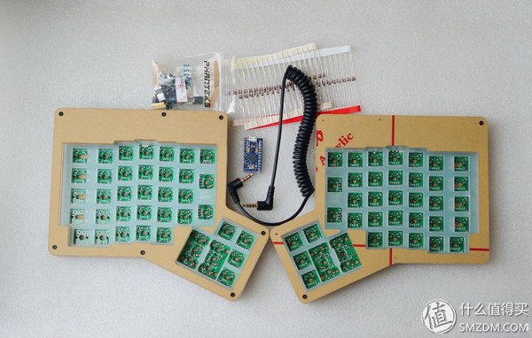
In addition to the above, it is necessary to assemble it with its own shaft, satellite shaft, keycap, and welding tool. In addition, a miniUSB cable must be provided. The principle of not adopting microUSB is that the miniUSB is relatively stable.
The two PCBs are actually the same, used on both sides, one for the left hand and one for the right hand.


All components need to be self-welded, and all use non-patch components, so the welding difficulty is almost the same as the welding axis, but it takes more time for DIY. This is also a way to reduce costs.
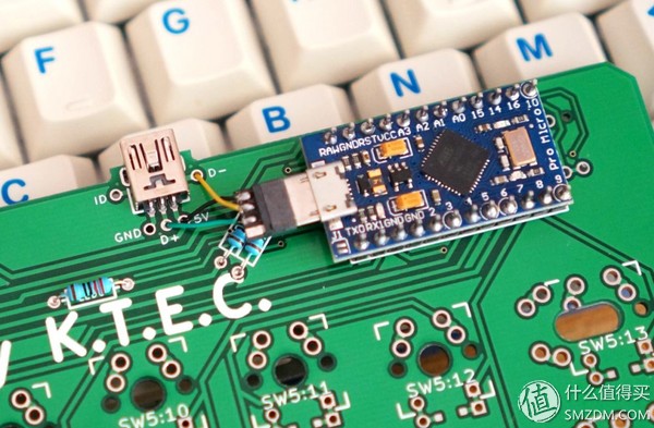
[Part 2.Assembly]The first step is to weld first. Beginning with the main hand, first weld the main control. I first weld the pin to the master, then solder it to the main hand's PCB, and notice the mark and direction on the PCB. The excess part of the pin can be cut off or it can be retained, and the cover can be put down when it is left.
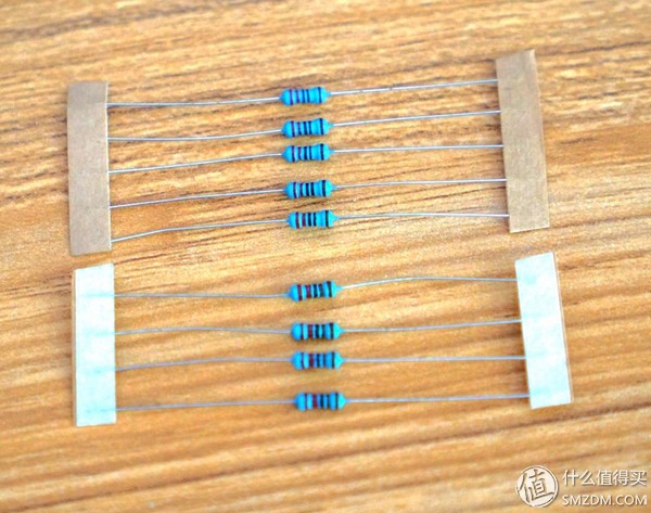
The next welding resistance, a total of 5, two 2.2k Europe, there are three for the LED indicator. Resistors, people will see the resistance directly from the resistor shell can see the resistance, will not see the map to rely on the following to distinguish it. The following is 2.2k Europe, and the other is the 220 Euro used by the LED.
The miniUSB interface on the PCB is also soldered.

Then here we need to find a few wires, as shown below, pay attention to the interface correspondence. At least three of D+, D-, and +5v need to be soldered. This connects the USB interface on the PCB to the main control of the keyboard. After soldering, plug in the computer and try to identify it. Then continue.
Welded these lines, in order to look good, I first left the line longer, straightened from the back of the PCB, and then welded.

Then welding 3.5mm audio interface, the main part of the main part of the core welding. When the 3.5mm audio interface is soldered, it needs to be processed, and polished on both sides. It can be polished with a guillotine or sandpaper or on a concrete floor, or it can be cut off with a small knife. Put it into the shell, as shown below, the upper and lower sides will not lift the shell.


In addition, the jumper on the front of the PCB and the audio port must be soldered. At this time, no soldering is required. After the housing is mounted and the shaft is welded, the soldering is not as convenient as it is now.

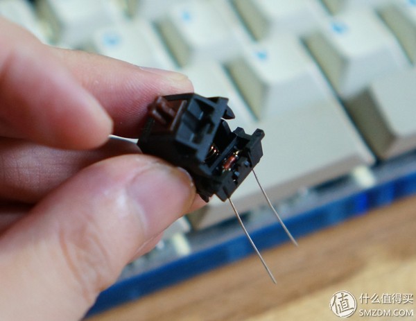
Then, it took more time to work - soldering diodes. Diodes are divided into positive and negative electrodes. Take this diode as an example. The red color is positive and negative, and the black color is negative. Then, corresponding to the PCB, the square pad is the positive electrode, and the circular pad is the negative electrode. Diodes can be soldered on the backside and can also be used as in-shaft diodes. Here we soldered on the back side as an example.
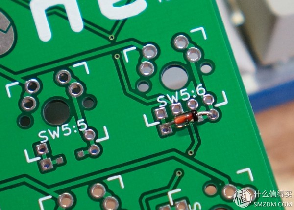
Each diode bends the leg, cuts off the excess leg, and then solderes. Pay attention to the front of the PCB during soldering. Do not allow the solder to protrude. When the soldering shaft is in place, it will resist the positioning plate.
After welding the diodes, the upper shaft can be started. There is a very important thing here, the positioning plate, and the positioning plate must be mounted on the shaft and the welding shaft. Among them, the 2x large key position is designed to use a detachable satellite shaft. Therefore, the use of a five-legged axis is recommended. In fact, I also recommend that all use a five-legged axis.
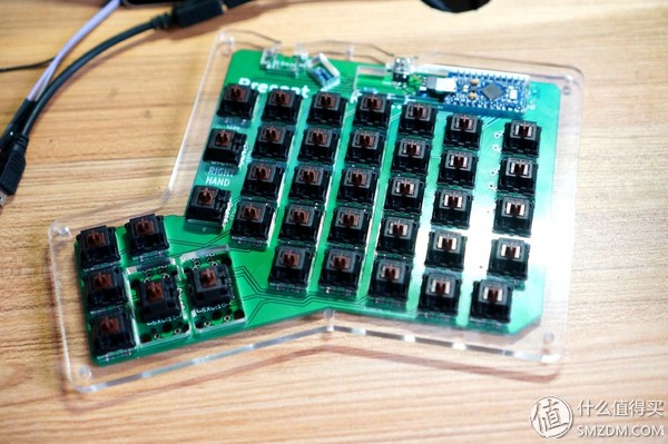
After welding the shaft, there are three axes that can hold the lamp and support three indicators. After the shaft and the lamp are all soldered, the shell can be installed after testing the function. The satellite shaft of the 2x key position must be remembered.
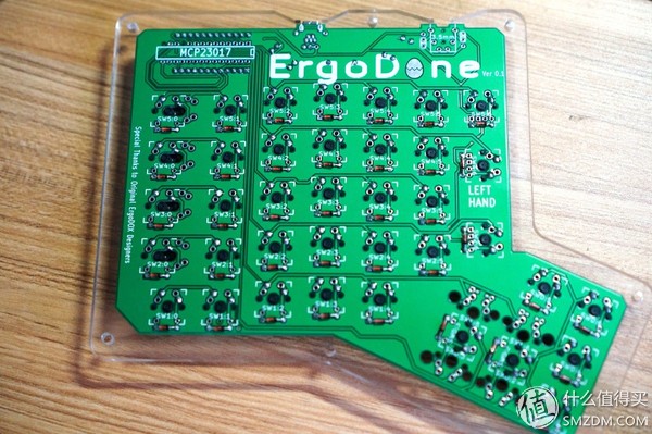
The main part of the above hand is completed. The core part of the deputy is mainly to weld the mcp23017 and a 3.5mm audio jack. When mcp23017 pay attention to the direction. When I solder the deputy, use the in-shaft diode. Open the shaft cover first, not to find a tutorial online, and then put the diode into the shaft, the shaft diode is cherry original keyboard practice. If both the left hand and the right hand use an on-axis diode, be aware that the diodes in the two axes are different in direction.
The diode in the shaft must pay attention to the correct direction. If it is reversed, this button cannot be used, and it is necessary to change the direction of the diode again to disassemble the shaft and change it again.
All that's left is time, installing all the diodes, soldering the shafts and diodes, and cutting off the extra diode pins.

As mentioned earlier, the deputy direction of the mcp23017, when welding the attention of the silk screen on the PCB markings, and the corresponding components, this welding will be difficult to remove the anti-, remember not welding reverse. Production version of the PCB, next to mcp23017, there is a capacitor to be welded.

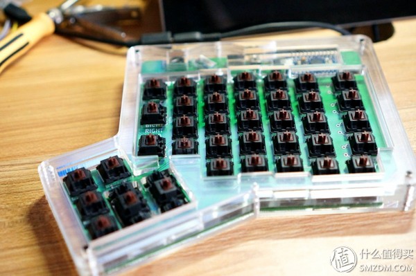
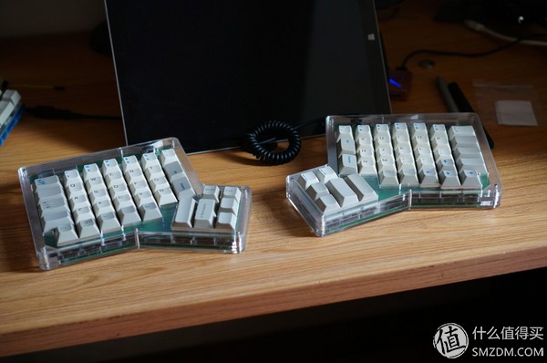
After all of them have been soldered, the same test can be done with the key connection. I've put together some of the keycaps that I've put together. After all, I'm poor, so please don't give me a Tucaim keycap.
The next step is to use, ErgoDone uses TMK-based TKG to do firmware, and the key change mode is the same as most domestic custom keyboards (such as GH60). Brush machine made some improvements.
The first is to change the button, use the Keyboard-Layout-Editor, set up the keys you want to use.

Then copy the raw data or the url that holds the layout to tkg, and then set the Fn button and the LED light function to open the brush.
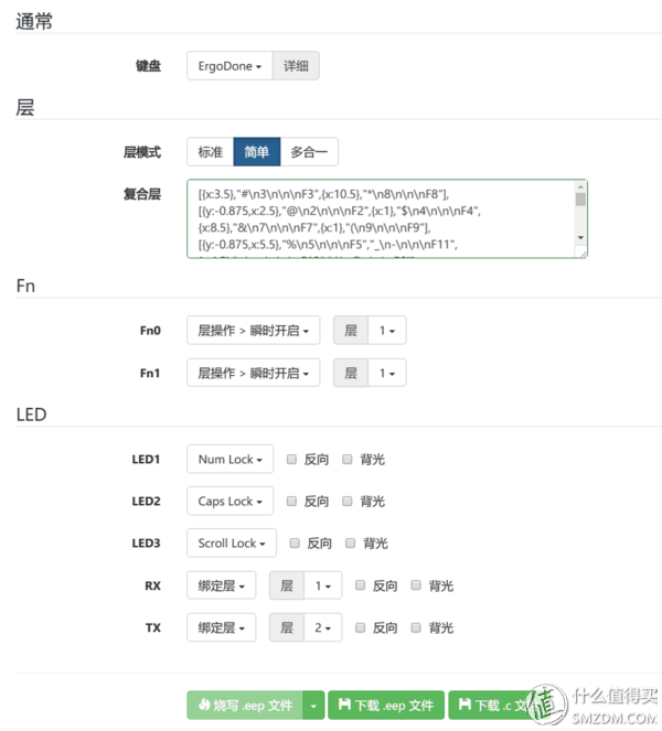
You can use online or local flash. Online Flash only supports chrome browser. This method is recommended. Follow the prompts to install the TKG Chrome App. The default bootloader used by the second dog is the HID bootloader. You do not need to manually install the driver as you would with the GH60, and you do not need to reset the keyboard's reset button. The usage method is as shown in the figure below. Take the mass production version as an example, insert the data cable while holding down the key to enter the firmware mode.
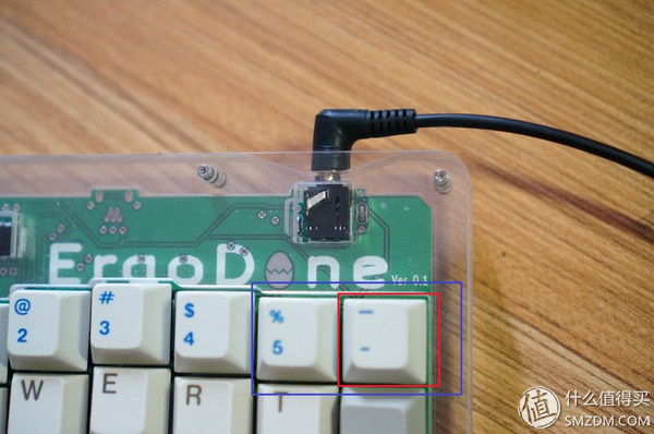
Press and hold the key in the red box to insert the data cable (after inserting the data cable, the computer finds the new hardware, you can release the button). It is the brush eeprom, generally just modify the button, and only use this mode. When using the online brush, the device found in the pull-down menu will be ErgoDone HID EEPROM, then directly “flash the .eep file†to complete the refresh online.

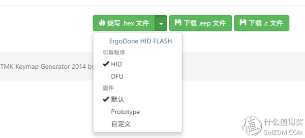
At the same time hold down the two buttons in the blue box and then insert the data line, is to brush FLASH, this part generally do not need to be updated, there will be a notice of the update. When using the online flash to update FLASH, you need to hold down the shift key of the keyboard (using another keyboard available on the current PC). At this time, the button will change to "Write.hex file". Click it to refresh the latest firmware online. .
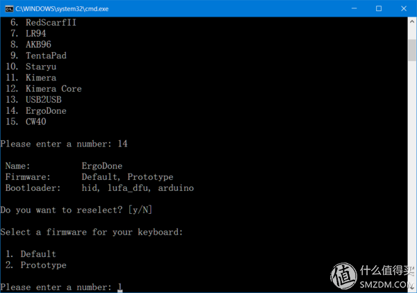
Similarly, you can use tkg-toolkit to refresh locally like gh60. Download the latest tkg-toolkit on github. The latest one already supports ErgoDone. Then after a few steps of the settings, select the keyboard to be brushed, and keep everything else by default. When using the local brush, simply drag the downloaded keymap.eep file to reflash.bat. The method of entering the brush eeprom is the same as that of the online brush. Also, it is not necessary to install any driver manually.
After all, this is not a tutorial, so this section is just a brief introduction.
Not particularly skilled, it is estimated that the time needed to set up an ErgoDone is about five hours. The difficulty is not so great. All the components are soldered in the form of plugs. There is no patch. Basically, the shaft is welded. Patience is a bit. Welding the entire ErgoDone is not a problem. The keycap is currently used by some domestic people who will do ErgoDox's matching keycaps. It is also fully applicable to the ErgoDone written in this article. Now it has been sold for a while.
Then I talk about the use of feelings: after the two sides split, the left and right hands can easily place the position and angle, after adjustment, the keys, the wrist will be a lot more comfortable. But for the key arrangement, from the regular keyboard to the second dog, it takes a certain amount of time to adapt. The main thing that needs to be adapted is the change in the position of the Z-line. When I start the left-hand part of the Z-line, more than half of the time will be wrong.
Add to the approximate DIY cost.
Kit: 199; axis: 276 = 152 yuan, if using the Gateron axis, it is 76 yuan; satellite axis: 5x4 = 20 yuan; key cap: 119 yuan. 500 can be won.
Commercial Lighting Led Driver
Commercial Lighting Led Driver
With Commercial lighting tend to be led lighting mode more and more, led lighting solutions became the most verriding concern issue at the lighting area. We have skilled engineers to answer all your questions and enquiries and provide all-round solutions basis on your project(s) and provide technical supporting. Energy saving and environmental protection are always Fahold's aim, Specializing in LED lighting drivers design, Products apply to street light, industrial and mini light, linear light, tri-proof light, flood light, panel light and so on.
Parameter:
Input voltage: 100-277vac / 100-240vac / 100-130vac / 180-240vac / 100-347V
output voltage: 25-40vdc / 27-42vdc / 35-45vdc / 50-70vdc / 12Vdc / 24vdc
current: 100mA-8000mA.
Power factor: >0.95
Dimming: 0-10V / PWM / RX / DALI/Traic dimmable
>=50000hours, 3-5 years warranty.
certificate: UL CE FCC TUV SAA ect.

FAQ:
Question 1:Are you a factory or a trading company?
Answer: We are a factory.
Question 2: Payment term?
Answer: 30% TT deposit + 70% TT before shipment,50% TT deposit + 50% LC balance, Flexible payment
can be negotiated.
Question 3: What's the main business of Fahold?
Answer: Fahold focused on LED controllers and dimmers from 2010. We have 28 engineers who dedicated themselves to researching and developing LED controlling and dimming system.
Question 4: What Fahold will do if we have problems after receiving your products?
Answer: Our products have been strictly inspected before shipping. Once you receive the products you are not satisfied, please feel free to contact us in time, we will do our best to solve any of your problems with our good after-sale service.
Commercial Lighting Led Driver,Constant Led Driver Circuit,Led Lighting Solutions ,Led Driver Power
ShenZhen Fahold Electronic Limited , https://www.fahold.com