AD sampling based algorithm
This article refers to the address: http://
The black line extraction algorithm based on AD can reflect the black and white degree of each point on the image, and the extracted black line has higher accuracy, but the subsequent black line extraction algorithm is more complicated. Software black line extraction based on voltage jump comparison method is very simple, but hardware debugging is difficult, and can not reflect the true black and white degree of each point. The track environment is very demanding and susceptible to interference.
There are several methods for extracting blackouts based on AD:
1) Find the left and right boundary points of the black line of each line, and use the middle point as the road;
2) Add a few lines and take the blackest point;
3) Find the darkest point of each line and use it as a road.
The first method: Find the left and right boundary points of the black line of each line, and use the middle point as the road.
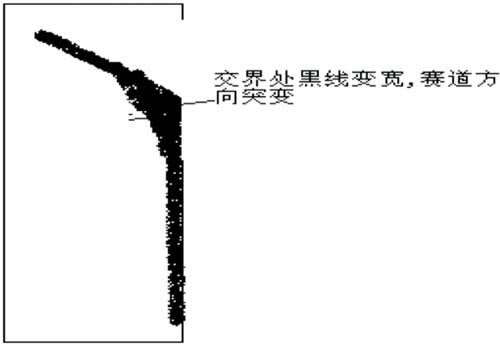
Figure 1 Schematic view of the crossroad
It is the easiest way to think of it. It can achieve very good results without a crossover and the black and white AD value of the camera. But if there is a diagonal crossover or the black and white AD is not very clear, The filtering of the method is very complicated. In practice, the camera is not very sensitive to the black line in the distance, which makes the threshold of the black point difficult to determine. If the selection is large, the remote road will be extracted incorrectly. If it is small, it will lose the distant road. Information. Perhaps using a dynamic threshold is a good method, but it is not very useful. In the experiment we found that the threshold of the black point does not change linearly with the distance, how much it changes with the taste of a point mutation, so it is very It is difficult to determine the change rule of the black point threshold, and the natural dynamic threshold is also difficult to set. Oblique viewing of the cross will bring more trouble, because it is difficult to strictly stick the line every time in actual control, so When the car comes out of a corner, if there is a cross in front of the curve, it is easy to cause a slanting situation. At this time, from the image captured by AD, the cross will look like a forked branch. The same thing comes out from the road ahead. The worse situation is that the right road disappears in front of the right side of the cross road. If you use this method, it is easy to mistake the road to the side of the cross. On the top, the steering error of the car. In order to filter out this situation, we use a lot of filtering methods according to its characteristics.
First of all, at the junction of the road ahead and the cross, the number of black points will suddenly increase a lot. Under normal circumstances, as the distance increases, the number of black points will gradually decrease, and there will be no sudden increase. So we can use the number of black points on the previous line to estimate the number of black points on the next line. If we exceed our estimate, we think it is unreasonable.
Secondly, according to the principle that the track does not change, we can filter out the noise. We can predict the range of the next line according to the changes of the previous two lines, and use it to filter out the noise. But in the actual application The change range prediction for a row is not always ideal. So when the car passes the 90-degree bend, the change in the track is very large in the car's view. It is almost no different from the diagonal cross. Sometimes it will be 90 degrees. Bending and filtering, causing the car to directly rush out of the runway.
Finally, we can also search for the left and right boundary points of the track by left-to-right and right-to-left methods. If the two are found to be inconsistent, we can take the point with less change as the track.
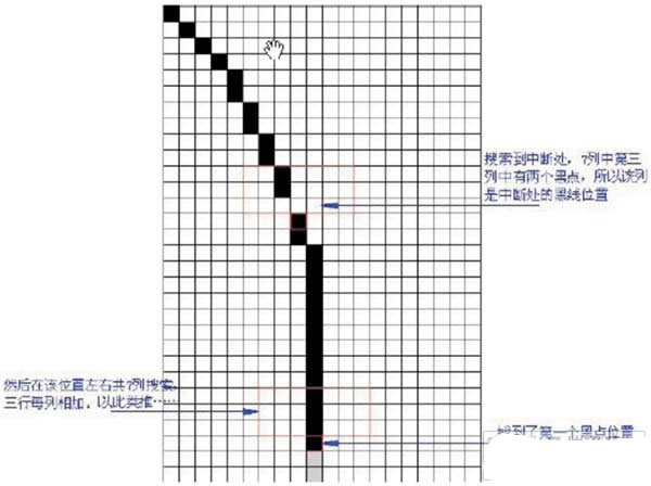
Figure 2 Schematic diagram of adding three lines to extract black lines
After adding the above filter, it is very complicated to search the track program, and it is not very reliable.
The second approach: Add several lines and take the blackest point.
This is the algorithm proposed by our previous seniors. But I am not very reliable in using it. Its head point is always unstable. The reason for the addition of its three lines is that if the black line in the middle row is lost, it can Use the threshold you set yourself to retrieve it. For example, the black point threshold added by three lines can be defined as the sum of 1 white point and 2 black points. With some median filtering taste. However, due to the black and white in the distance It is not very clear that the threshold of black and white is difficult to set, and the threshold of adding three lines is more difficult to set. And because there are fewer points on the curve due to the distance, there are only one or two black points and they are not on the same column. It is easy to lose these points, causing the points on the head to be unstable. In order to extract the distant black lines as much as possible, the only way to increase the threshold from the software is to increase the threshold, for example, the threshold for adding the three lines is set to A black and white add, but the problem is that the black and white in the distance is not very obvious, the white point is darker, the black point is whiter, and the selection of this threshold is easy to cause the black spots in the distance to be black. Among the lines, this made the steering of the car confusing.
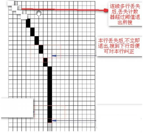
Figure 3 Finding black spots line by line
The third way: Find the darkest point of each line and use it as a road.
Since each line searches for the blackest point, the threshold of the black point can be slightly expanded a little. Even if the black and white in the distance is unclear, it is still possible to extract the true black line because it is the blackest point. Its main problem Yes, not every line has a point that meets the requirements, which will cause a line to be lost and lose the black point behind. The solution is to not immediately exit the search after finding a line is lost, but to set a lost counter, only when the counter is lost. The value is continuously added to a certain threshold before exiting. Whenever you search for a black line of a line, look at whether the lost counter is non-zero. If not, it means there is no missing line. If it is, then there are several lines missing. We can linearize the missing lines in the middle of the missing row pair with the effective row pair. Then we clear the missing counter. With the missing counter, we can strictly control the extraction conditions of the track. Limit, without worrying about the black line missing. For example, we can strictly limit the width of the black line, so we can easily filter out the interference caused by the large black spots; for the above Looking at the problem of the cross line, we can easily filter out the range of the next line of black lines according to the black line of the previous line. Of course, after finding the missing line, the search for the next line must increase the range of the black line search. The more consecutive rows are lost, the lower the credibility of the black line retrieved again. In the actual extraction process, this threshold must be grasped so that the road ahead can be found smoothly without erroneously extracting the black line. It has been proved that this method is simple to implement, has the highest reliability, and the black line extraction is very stable.
Hardware filtering (voltage jump comparison)
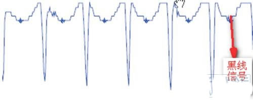
Figure 4 video output signal of the camera
From the video output signal of the camera, we can see that there is an obvious voltage jump between the black line and the white line. We can use this feature as the extraction mark of the black line. We can change the hardware circuit with reasonable hardware. Realize the output logic 1 before the voltage jump, and output the logic 0 after the voltage jump. So the microcontroller needs to constantly read the level state of the pin. Since AD ​​conversion is not required, this makes the MCU in each video. The line break reads a lot more points than AD, and the number of black points is naturally many. The software to extract black lines is to distinguish between 0 and 1 and it is very convenient to implement. Below is a picture The contrast between the image extracted by the method and the AD sample image.
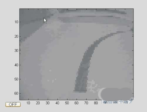
Figure 5 AD sampling diagram
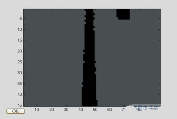
Figure 6 hardware sampling diagram
You can see that its black line is very obvious and works well.
But this method also has many limitations:
First of all, it is very demanding on the environment, there can be no seams, no reflections. Since the color of the seam is obviously easy to surround the color, it appears as a black line on the image. Secondly, due to the effect of reflection, the light in the reflective area is extremely strong. The reflective area is also black on the image, making the white black.
Second, its ability to resolve horizontally is weak. It makes it very difficult to distinguish the starting track. For example, the starting track on the image tends to turn the middle black channel into a white track, making the identification of the starting track and the extraction of the black line difficult.
Finally, for a crossroad, since the line is all black lines, the voltage does not jump, so it is a white line on the image, causing a breakpoint on the track. Black and white appear. Worse case is a slight oblique cross When it forks, it will appear the characteristics of the starting track, causing the car to stop.
The above-mentioned black and white and white black appear to largely offset the convenience brought by it. The software must carefully discriminate whether the black line is black or not, which involves many In terms of filtering, in addition, since the MCU reads only the 0-1 signal, the slight black and white degree between each point is lost, which brings great difficulties to the filtering. In order to correctly extract the black line, it involves All the filtering methods mentioned in this article, including line width settings, black line continuity, and so on.
However, the biggest difficulty it brings is the discriminating problem of the starting track. The interference of the starting track is not only from the cross line, but also from the general track, because it is likely to be caused by the uneven reflection of light on both sides of the track. The jump of the voltage causes a few black lines to appear alongside a black line next to the black line. It is easy to misidentify the starting track, and eventually the starting track is not recognized at all.
Based on the above analysis, we finally chose the third method of AD, which is simple, practical and effective.
Its flow chart and program code are as follows:
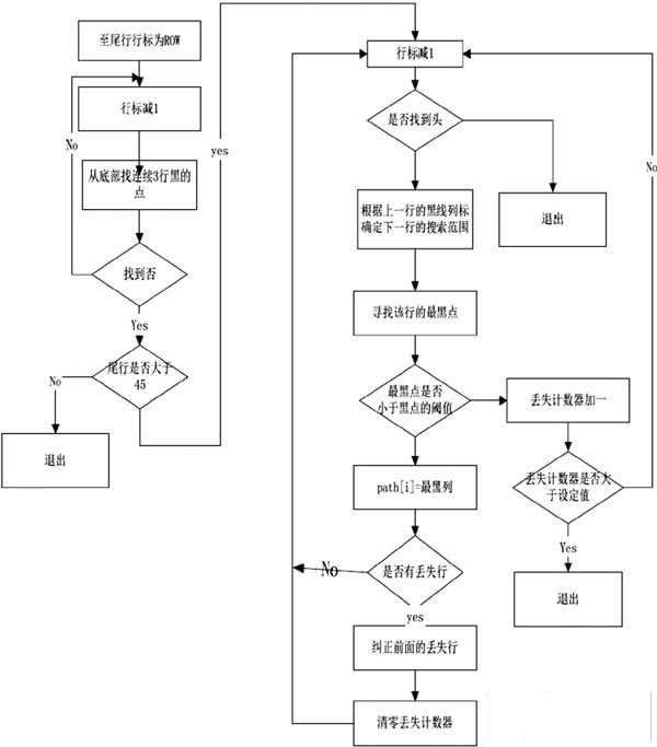
Figure 7 flow chart
references
[1] Zhuo Qing, Huang Kaisheng, Shao Beibei, etc. Learn to be a smart car - challenge the "Freescale" Cup. Beijing University of Aeronautics and Astronautics Press. 2007
[2] The 2nd National Undergraduate "Freescale" Cup Smart Car Competition Zhejiang University Jaguar II Team Technical Document
[3] The second national college student "Freescale" Cup smart car competition Shanghai Jiaotong University speedstar team technical documents
Our company offers rubber, and specialty seal and o-ring for molding electronic and electrical Connectors, both circular and rectangular types. We have in house capabilities and quick turn around.
Cable Grommets with various Grommet Shapes, Rib Styles, Slot Shapes, Inner Flanges, and Colors - To have access to our 3D Cable Grommet Design Tool
Silicone Rubber Products,Cable Silicone O-Ring,Rubber Seal,Custom Silicone Seal,Waterproofing O-Ring,Tpe Grommet
ETOP WIREHARNESS LIMITED , https://www.etopwireharness.com