This paper mainly studies the automatic driving control method of unmanned vehicles.
This article refers to the address: http://
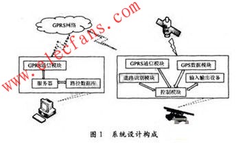
1 system design
The system is mainly composed of a monitoring center and is shown in Figure 1, while the unmanned vehicle terminal includes GPS, GIS, GPRS and other parts:
(1) GPS (Global Positioning System) is a satellite network composed of 24 artificial satellites, which can continuously transmit positioning and time signals to the Earth. Any GPS receiver on the earth, as long as it receives more than 4 satellite signals, can calculate the position (latitude, longitude, altitude), time and motion state (speed, heading) of the GPS receiver after calculation. This system uses GPS to enable the vehicle to accurately display its position while driving.
(2) GIS (Geography Information System) is information that collects, stores, manages, calculates, analyzes and visualizes geographically distributed data of all or part of the Earth's surface space with the support of computer hardware and software systems. Process and manage the system. In this system, he is combined with the GPS module to provide dynamic electronic maps in the computer system based on geospatial data, and can display the traffic information to the user in a friendly manner through the GIS interface in real time.
(3) GPRS (General Packet Radio Service) is a professional high-speed data communication network superimposed on the network of GSM (Global System), sharing GSM frequency (900/1 800 MHz). Sharing most of the infrastructure of the GSM network. It can access the external network based on TCP/IP and has all the functions that the Internet can provide. This system uses GPRS as the wireless communication bridge between the vehicle terminal and the monitoring terminal, mainly considering He has several advantages such as high resource utilization, high transmission rate, short access time and wide network coverage.
(4) Radio frequency identification card reader. Radio frequency identification technology is generally used in transportation systems for non-stop charging on highway stations, automatic identification of license plates or scheduled parking charges. These systems place the tag on the vehicle terminal, install the antenna, RF module and computer on the ground, and use the reader in the RF module to perform a certain range of radio frequency identification. The RFID module determines whether a vehicle has passed by installing a target vehicle proximity sensor. The identification module generates a microwave signal in a certain area, and when the vehicle enters the identification area, the label can be activated. The tag reflects the data to the identification module, and the RF reader completes the data reading.
2 vehicle terminal hardware composition
The vehicle terminal is composed of a GPS receiving module, a GPRS receiving device, a main control module, a card reader module, a display module and an input operation module, and the system framework is as shown in FIG. 2 .

(1) The self-suspended monorail body is equipped with an embedded control system, which is mainly used for the control of the entire vehicle and the scheduling between the various modules. The main control module chip uses the LPC2000 series processor manufactured by Philips, which is based on a 16/32-bit ARM7TDMI-STM CPU microcontroller supporting real-time simulation and tracking, with a high speed of 0/128/256kB embedded. On-chip FLASH memory. The on-chip 128-bit wide memory interface and unique acceleration structure reduce the 32-bit code size by more than 30% with minimal performance loss.
By extending a series of complete general-purpose peripheral devices based on this series of processor chips, the system hardware cost can be minimized, and the reduction can be made according to the design requirements, which can provide a low power consumption and low cost for the in-vehicle system. High performance solution.
(2) The system maintains a connection with the Internet by means of GPRS wireless transmission and exchanges data with the rail transit information website. The system adopts the M22 module produced by BenQ. It conforms to the ETSIGSM phase 2+ standard and AT command set, and supports GSM voice data fax short message and GPRS data transmission.
(3) The display module is mainly used to display the driving state of the vehicle, including the geographical information location, the path collection situation, and the like. This system uses TFT6758 liquid crystal display module, working voltage is 3.3 V, with white LED backlight inside. Since the LCD module contains the HD66781 and HD66783 LCD control drivers, it can be connected directly to the controller using an 8-bit, 16-bit or 18-bit bus.
(4) The input module function is to refer to the path information received by the card reader through the button.
(5) The GPS module is used to locate the vehicle. The system uses M12 positioning module, Motorola's navigation equipment, has low power consumption, supports the differential function of RTCM (Radio Technical Commission for Maritime) format, and uses NAEA0183 format output. The receiver is widely used in automotive positioning and dispatch systems.
3 terminal software part programming
This system uses ARM7 as the main controller, taking μC/OS-II as the operating system in consideration of resource utilization. μC/OS-II is a complete, portable, curable, and tailorable preemptive real-time multitasking kernel. He writes in ANSI C and contains a small amount of assembly code that can be used by microprocessors of different architectures. μC/OS-II can manage 64 tasks with semaphores, mutual semaphores, event flag groups, message mailboxes, message queues, task management, time management, and memory block management.
The μC/OS-II software architecture has three parts:
(1) μC/OS-II core code: including 10 C program files and 1 header file, mainly realize system functions such as system scheduling, task management, memory management, semaphore, message mailbox and message queue. This section is independent of processor performance.
(2) μC/OS-II configuration code: Includes two header files for cutting and configuring μC/OS-II. This part is related to the actual application of the user.
(3) μC/OS-II porting code: including 1 assembly file, 1 C program file and 1 header file, which is the code required for porting μC/OS-II, regardless of the processor.
In this system, the system migration is first performed in order to make the program call. The migration meets the following requirements:
(1) The processor's C compiler can generate reentrant code;
(2) The processor supports interrupts and can generate timing interrupts (10 to 100 Hz);
(3) It can be turned on/off in C language;
(4) The processor can support a certain number of data storage hardware stacks (possibly a few kB);
(5) The processor has instructions to read and save the contents of the stack pointer and other CPU registers to the stack or memory.
The system software program is mainly divided into three parts: the input part, the control part and the output part. The following is introduced separately.
The input device mainly includes a keyboard, a radio frequency identification card reader, and a receiving system constituting the input device: a GPS/GIS receiver and a GPRS module. During the driving process of the vehicle, the radio frequency identification module is responsible for correctly receiving the road condition information, the keyboard is responsible for waiting for the user to receive the user instruction on the vehicle, and the GPRS module is responsible for receiving the data information of the remote workstation. After the startup, the module is mainly responsible for contacting the workstation and performing the connection. Information exchange, and constantly update part of the path information in the system, so that the vehicle can turn in time. The GPS and GIS modules are primarily responsible for enabling the system to receive the current accurate location of the vehicle.
The output device mainly includes a display screen, etc., and obtains the location of the vehicle and the road condition information through the display screen. His main function is to output the corresponding high and low levels according to the requirements to provide the voltage required for steering. The realization principle is that the system generates high and low levels by obtaining data information from the tag. At the same time, the system must display the data provided by the GPS module and the GPRS module on the screen through the man-machine interface so that the user can see the information of the vehicle in real time, including the front. Road conditions, vehicle location, etc.
The control part is the key to the system, and the flow chart is shown in Figure 3.

The flow of the control part is as follows: first download the operating system to the target board, initialize the target board, and set the interrupt vector of each module to ensure that each module can run correctly after startup. The priority of interrupt priority is the highest priority of the reader, followed by GPRS, and finally GPS. At the same time, the display shows the operation interface, and the user can input commands to start the car. When the vehicle is started, each module will also run, and the system program will go into the inquiry state. By continuously scanning the UART port, it is judged whether or not a tag enters the identification area. If the label recognition area is entered, the card reader will receive the barcode signal recognized by the RF module. After the signal is correct, the system will transfer the interrupt subroutine. In the interrupt subroutine, the system provides the corresponding high and low levels to the GPIO port as the output signal to achieve steering. GPRS is activated as soon as the vehicle is started, because he must constantly update the path information provided by the monitoring center to ensure the normal running of the vehicle. When the vehicle stops, it will send a level signal. At this time, the system goes into the waiting state, and the screen displays the operation interface, waiting for the user to proceed to the next step.
4 Conclusion
The test and simulation of this scheme show that the autonomous steering suspension monorail can recognize the front track information through the RF module at a frequency of 915 MHz within 10 m of the distance label, and can connect with GPRS at a baud rate of 115.2 kB/s. Then, the access GPRS network communicates with the remote network monitoring station in real time to exchange data. At the same time, the system can make a judgment and issue a control signal. According to the test, the system has high stability and strong real-time performance. If it can be applied to the actual situation, the user and the workstation can understand the working state of the vehicle, which has great significance for reducing traffic accidents.
Kara offers a wide range of illuminated and non-illuminated Rocker Switches.In this series,Rated current 6A,10A,16A,Ranging from 1 to 6 poles,with many styles of colors and functions. Certifications include UL, CSA, TUV, CE, and more.
Why choose us?
1)As a manufacture, all of our switch parts are made by our own factory in Ningbo. So, price is competitive.
2)We have our own UL testing lab in Taiwan, so quality can be guaranteed.
3) We can provide you with different types of rotary switches for your selection.
4) Various operating force,height and colour for one switch for your choice.
5) Safety, on-time delivery, excellent quality with competitive price.
6) MOQ: 1000pcs,mixed order acceptable, welcome trial order.
7) OEM and ODM professional design.
8) We can provide free samples for your test.


Small-Sized Rocker Switches,Round Rocker Switch,Small Rocker Switch,Mini Rocker Switch
Ningbo Kara Electronic Co.,Ltd. , https://www.kara-switch.com