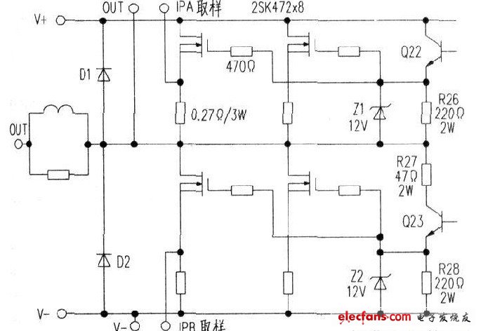
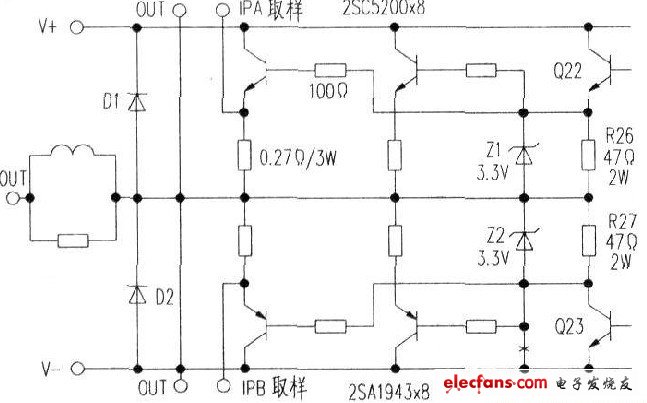
Take the ODL brand QSA-2400 professional power amplifier as an example (see the figure in the circuit). The corresponding circuit after modification is shown in the figure below. Due to the difference in driving voltage between the MOS transistor and the triode. In order to ensure that the static operating point of the voltage push tube remains basically unchanged, the resistance values ​​of R26 and R27 should be reselected. The voltage on the original emitter resistance of the Q22 transistor is 3V. It is now changed to O.57V. The original transistor Iem=3V/220Ω=13.6mA. The emitter resistance of the transistor is now Re=0.57V/13.6mA=41.9Ω and 47Ω/2W. Push board modification: Change R26 and R27 to 47Ω/2W resistors. Short the R28. The negative power MOS transistor drive voltage is changed from the R27 resistor terminal.
This article refers to the address: http://
High-power current output pole modification: Transistor corresponds to MOS tube electrode position: b pole to G pole. c pole to D pole. e pole to S pole.
Before the modification, it is necessary to confirm that the MOS tube pin arrangement 2SK427 pin arrangement function is consistent with the A1943/C5200, and can be directly installed. The high-power resistor does not move, the G-pole resistance is originally 470Ω, and it is changed to 100Ω after the triode is installed, and it can also be short-circuited. The protection voltage regulator diode between the original OUT-G is 12V, which is now changed to 3.3V. See the figure below for correction.
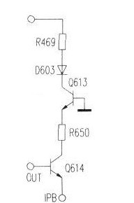
Protection circuit changes: see the picture on the right and the picture above. Negative power MOS tube overcurrent protection sampling voltage is the source load resistance. The sampling connection is G pole and v-. After changing to a triode, the sampling voltage is a PNP type high power tube emitter load resistor, and the sampling connection is OUT and e pole. The negative Power Supply high-power tube over-current protection action tube Q614 is originally connected to the base Ipb, and the emitter is connected to V-. Now change the b pole of Q614 to OUT, and the e pole to Ipb.
Selection of high-power triodes: Due to the high operating voltage and high reliability requirements of professional power amplifiers, the triode withstand voltage should be greater than 200V.
The power output of the power amplifier is required to be no less than 500W. Pipe consumption Pemax = 0.2 Psc = 0.2 x 500 = 100 W. According to the safety parameters, choose Toshiba A1943/C5200 high-power audio tube. Its parameters are: Uceo = 230v, PCM = 150w. In order to ensure the sound quality, the static working point is set to Class A and Class B. Each power amplifier tube static working current Iem = 37mA. At this time, the corresponding Vbe voltage is 0.57V. Calculate the static power consumption of each tube as:
100v x 37mA = 37w. Each channel has 16 high-power tubes, and one channel has a static power consumption of 16 × 3.7 = 59W.
Â
12V Adapter,Power Supply Adapter,Laptop Power Ac Adapters,Linear Desktop Power Adapter
Ninghai Yingjiao Electrical Co., Ltd. , https://www.yingjiaoadapter.com