Here I introduce a simple and easy to learn drawing method for your reference.
Usually, the branch where each diode is located is called an arm, so that the bridge rectifier circuit has four arms.
1. Drawing method (mouth)
The two arms are oriented in the same direction (diode), one positive and one negative (connected) are connected to the alternating current, two positive (connected) are the negative of the direct current, and the two negative (connected) are the positive of the direct current.
The specific instructions are as follows:
(1) ab, cd, bc, and ad are four arms.
(2) Ab and cd, ad and be are opposite arms, and V1 and V3, V2 and v4 diodes (positive or negative) are oriented in the same direction.
(3) The point d in Fig. 1 is the point at which the negative electrode of V4 is connected to the positive electrode of v3. Point b is the point at which the positive pole of V2 is connected to the negative pole of V1.
These two points are connected to alternating current. Point a in Figure 2 is the point where the negative pole of V4 is connected to the positive pole of V1, and point c is the point where the negative pole of V3 is connected to the positive pole of V2, and these two points are connected to alternating current (one positive and one negative alternating current).
(4) The a point of the positive electrode of V4 in Fig. 1 connected to the positive electrode of V1 is the negative electrode of direct current; the point d of the positive electrode of V4 in Fig. 2 and the positive electrode of v3 is the negative electrode of direct current (both positive and negative of direct current).
(5) The point C of the negative electrode of V3 and the negative electrode of V2 in Fig. 1 is the positive electrode of direct current; the point b of the negative electrode of v1 and the negative electrode of v2 in Fig. 2 is the positive electrode of direct current (two negative are positive of direct current).
Thus, the complete circuit of the above two figures is shown in FIG. 3 and FIG. 4.
2. Application Example 1: Discrimination Figure 5 shows a rectifier circuit diagram in the form of a servo.
Solution: According to the above equivalent diagram of the circuit, it is shown in Fig. 6. It can be seen that it is a single-phase bridge rectifier circuit.
Example 2: Figure 7 is a circuit diagram of the power supply part of the rainbow TV circuit board.
Solution: According to the above-mentioned mouth, the circuit diagram is drawn as shown in Figure 8. 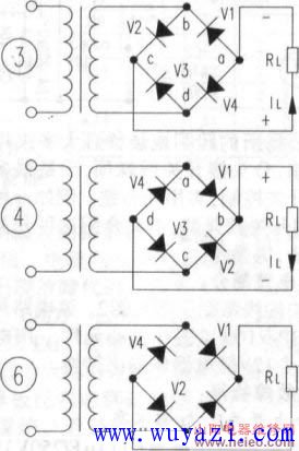
Fc To Lc Adapter,Fiber Cable To Ethernet Converter,Fiber Optic Adapter Kit,Fiber To Ethernet Converter
Ningbo Fengwei Communication Technology Co., Ltd , https://www.fengweicommunication.com