This article will introduce LED flashing lights, which are divided into single group flashing, two sets of alternating flashing and three sets of cyclic flashing. It also introduces a single set of flashing light circuit, two sets of alternating flashing light circuits, and three sets of cyclic flashing light circuit diagrams.
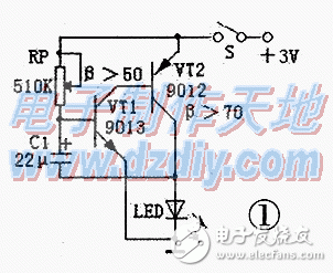
Single group flashing light circuit is shown in Figure 1. It belongs to the Rc oscillation circuit. The working principle is: when the power is turned on, the current is charged to C1 via RP, and the voltage on C1 cannot reach the turn-on voltage of VT1 immediately. VT1 starts to be in the off state, and VT2 is of course also in the off state, and the LED is not lit. When the voltage on C1 is charged to 0.7V, both complementary tubes are turned on, the LED is lit, and the charge stored on C1 is also released by the emission junction of VT1. When the base voltage of VT1 is reduced to 0.5V. Both complementary tubes are turned off and the LEDs are extinguished. The circuit is so repeating. The LED will flash in a blinking state. If the RP is adjusted to approximately 470 kΩ, the flash frequency is approximately 1 second. This circuit consumes very little power. If you use two No. 5 Nanfu batteries, you can use it for more than half a year to one year even if it is always on.

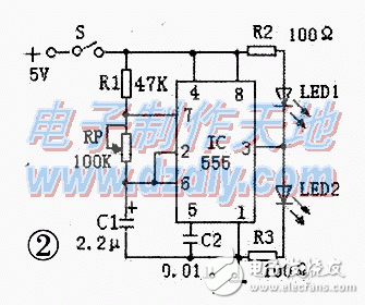
The two sets of alternate flashing lamp circuits are shown in Fig. 2. It is a multivibrator composed of 555 time base integrated circuits. The working principle is: at the moment when the power is turned on, the voltage on the timing capacitor C1 is 0v, the potential of the 2 pin is lower than (1/3) vcc, the output of the 3 pin is high level, the LED1 is off, and the LED 2 is on. After that, the power supply charges C1 via R1 and RP. When the voltage VC1 on C1 rises to (2/3) VCC greater than the reference voltage, pin 3 outputs a low level, LED1 illuminates, and LED2 turns off. In this way, VC1 periodically charges and discharges between 1/3 and 2/3 of Vcc, so that the level of the 3-pin is periodically hopped to form a self-oscillation. The oscillation frequency is the number of times the two LEDs flash every second. f=1.443/(R1+2RP)C. The operating voltage of the 555 time-base integrated circuit is 4.5 to 18V. The two current limiting resistors in Figure 2 mean 100Ω when using a 5v supply voltage.

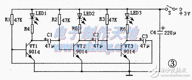
The three sets of cyclic flashing lamp circuits are shown in Figure 3, which is an unsteady self-excited multivibrator. The working principle is: when the circuit is connected to the power supply, the positive voltage is charged by the three-way LED, the current limiting resistors R4 R R6 and the transmitting junctions C1 - C3 of VT1 ~ VT3. Provides a base voltage for the triode. Although the values ​​of the three sets of circuits and components are the same. But the parameters of the components may not be exactly the same. Therefore, a triode must be turned on first. Assuming that VT1 is turned on first, a group of LED1 is illuminated, and C1 is reversely charged via the CE pole of R2 and VT1. When VT2 is turned off, LED2 will not light up. When the voltage on C2 is charged to 0.7V, VT3 is turned on and LED3 is lit. So reciprocating, there are always a group of LEDs in the three groups of LEDs that are extinguished. The two sets of LEDs cycle light. The cycle time can be adjusted by changing the values ​​of C1 to C3 and R1 to R3; if the value is large, the cycle is long.

The flashing lights described above. Under the premise of choosing the appropriate power supply voltage. Multiple LEDs can be connected in series or in parallel on the LED, but an appropriate current limiting resistor must be selected. When the LED is connected in series, the current limiting resistor can be calculated according to the following formula:
R=(U outside-UF·N)/IF
Where: R-current limiting resistor. U outside - applied voltage, UF - the forward voltage of each LED (such as φ5mm white LED UF is about 3 ~ 3.2v, limit voltage 3.9v; red LED UF is about 1.6 ~ 1.8v) . The operating current of the IF-LED, the number of N--LEDs connected in series. If using φ5mm high brightness LED. The working current can be 15~20mA. sometimes. The saturation voltage drop of the transistor (approximately 0.3V) should also be considered. If the LEDs are connected in parallel, the IF should be multiplied by the number of parallel LEDs; at the same time, the value of the limit parameter ICM of the triode should be considered, and the standard should not be exceeded and left blank. If the power supply voltage in Figure 3 is increased. The three base resistances can be reduced to 18kΩ to 30kΩ, and C1 to C3 can be reduced to 22μF to 30μF. At the same time, it is necessary to select a suitable high withstand voltage capacitor.
The flashing lamp circuit described above is simple, and the direct lap welding method can be used in the production. The beta value of the triode used should not be too low, and more than 80 can be selected. If there is no tube with a high beta value at hand, two tubes can be used instead of a composite tube.
Rf Duplexer,Coaxial Duplexer,Microwave Duplexer,Diplexer And Duplexer
Chengdu Zysen Technology Co., Ltd. , https://www.zysenmw.com