A basic LED classification and application
â— Classified by output power:
0.4 W, 1.28 W, 1.4 W, 3 W, 4.2 W, 5 W, 8 W, 10.5 W, 12 W, 15 W, 18 W, 20 W, 23 W, 25 W, 30 W, 45 W, 60 W, 100 W, 120 W, 150 W, 200 W, 300 W, and the like.
â— Classified by output voltage:
DC4V, 6V, 9V, 12V, 18V, 24V, 36V, 42V, 48V, 54V, 63V, 81V, 105V, 135V and so on.
â— Classified by shape structure:
There are two kinds of PCBA bare board and shell.
â— Classified by safety structure:
Both isolated and non-isolated.
â— Classified by power factor:
With power factor correction and without power factor.
â— Classification by waterproof performance:
Waterproof and non-waterproof.
â— Classified by incentives:
Self-excited and it excited.
â— Classified by circuit topology:
RCC, Flyback, Forward, Half-Bridge, Full-Bridge, Push-PLL, LLC, etc.
â— Classified by conversion method:
AC-DC and DC-DC are two.
â— Classified by output performance:
Constant current, constant voltage and constant current and constant voltage are three.
Application of LED driving power
Used for spotlights, cabinet lights, night lights, eye protection lights, LED ceiling lights, light cups, buried lights, underwater lights, wall washers, flood lights, street lights, signboard light boxes, string lights, downlights, and shaped lights Lights, Star Lights, Barrier Lights, Rainbow Lights, Curtain Wall Lights, Flexible Lights, Bar Lights, Led Lights, Piranha Lights, Fluorescent Lights, High Pole Lights, Bridge Lights, Miner's Lamps, Flashlights, Emergency Lights, Table Lamps, Lighting Fixtures, Traffic Lights , energy-saving lamps, car taillights, lawn lights, lanterns, crystal lamps, grille lights, tunnel lights and so on.
Second, the importance of LED drive power 
People who have contacted the LED know that: Because the LED has a very steep positive volt-ampere characteristic, Figure 1.1 (positive dynamic resistance is very small), it is difficult to provide normal power supply to the LED. Can not be like the ordinary incandescent lamp, directly use the voltage source to supply, otherwise the voltage fluctuation slightly increases, the electric current will increase to burn the degree of LED. In order to stabilize the operating current of the LED and ensure that the LED can work normally and reliably, a variety of LED driving circuits having "ballast function" come into being. The simplest is to connect a ballast resistor in series, and the more complicated one is a "constant current driver" made up of many electronic components.


A ballast resistance solution
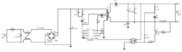
The schematic circuit diagram of this scheme is shown in Figure 1. This is an extremely simple, classic circuit that has been used since the advent of LEDs.
The LED operating current I is calculated as follows:
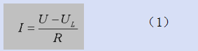
I is inversely proportional to the ballast resistance R; when the supply voltage U rises, R can limit I excessive growth, so that I does not exceed the allowable range of the LED.
This circuit has the advantages of simplicity and low cost; the disadvantage is that the current stability is not high; the resistance heating consumes power, resulting in low power consumption, and is only applicable to the low power LED range.
The formula for the ballast resistance R provided by general data is:
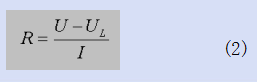
The R value calculated by this formula satisfies only one condition: operating current I. The other two important performance indicators for the drive circuit: current stability and power efficiency are completely ignored. Therefore, with its designed circuit, performance is not guaranteed.
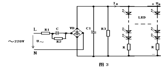
Two ballast capacitor solutions
The work of the circuit is based on the principle of the ballast action in the AC circuit. The capacitor XC also has a "ballast effect". In addition, the capacitor consumes reactive power and does not generate heat; while the resistor consumes active power, it will be converted into heat energy and dissipated. Therefore, the ballast capacitor can save a part of electric energy than the ballast resistor and can be designed to directly connect the LED light to the city. Electricity ~220V, more convenient to use.
The advantages of this scheme are simple, low cost and convenient power supply; the disadvantage is that the current stability is not high and the efficiency is not high. Only applicable to low power LED range. When the number of LEDs is larger, it is more suitable when the LED branch voltage is higher after series connection.
Trilinear constant current drive circuit
As mentioned above, the disadvantages of the resistor and capacitor ballast circuit are that the current stability is low (△I/I is ±20 to 50%), and the power efficiency is also low (about 50 to 70%). It is only suitable for low-power LED lamps. .
In order to meet the power needs of medium and high power LED lamps, a constant current drive circuit is designed by using the current negative feedback principle common in electronic technology. Like the DC constant voltage power supply, the constant current drive circuit is divided into two types, the linear constant current drive circuit and the switch constant current drive circuit.
Figure 4 is the simplest two-terminal linear constant current drive circuit. It uses a three-terminal integrated voltage regulator LM337 composed of constant current circuit, the periphery uses only two components: current sampling resistor R and anti-jamming capacitor C
Four switching power supply driving circuits
Although the linear constant current driving circuit has the advantages of simple circuit, few components, low cost, high constant current accuracy, and reliable operation, it also finds several disadvantages in use.
a. Adjusting the tube to work in a linear state, with high power consumption and high heat during operation (especially when the working pressure difference is too large), not only requires a larger size of the heat sink, but also reduces the power consumption efficiency.
b. The power supply voltage requirements are strictly matched with the LED operating voltage according to formula (13), and it is not allowed to change in a wide range. In other words, it has poor adaptability to changes in power supply voltage and LED load.
c. It can only work in the buck state and it cannot work in the boost state. That is, the power supply voltage must be higher than the LED operating voltage.
d, the power supply is not convenient, generally equipped with switching power supply, can not be directly used ~ 220V power supply.
Input rectification: change the positive and negative altering alternating current into a unidirectionally changing direct current
Filtering: smoothing a changing voltage waveform to a less fluctuating DC voltage waveform
Transformer: Stores energy and produces the required output voltage. The original and secondary sides are isolated.
Output Regulator: Stable Output Voltage
Sampling Feedback: The change of output voltage is reflected to the control circuit so that corresponding measures can be taken to ensure that the output voltage is within the specified range.
PWM + switch: control circuit, according to the feedback signal to control the amount of transformer storage energy, so as to ensure the stability of the output
The advantages of using a switching power supply drive: high efficiency, generally can be 80% to 90%, the output voltage, current stability. Output ripple is small. And this kind of circuit has perfect protection measures, it is a high reliability power supply.
LED drive power is mainly constant voltage and constant current
(1) Constant pressure type:
a. When the parameters in the voltage regulator circuit are determined, the output voltage is fixed, and the output current changes with the increase or decrease of the load;
b. The constant voltage circuit is not afraid of open load, but it is strictly prohibited that the load is completely short circuited.
c, to drive the LED with a constant voltage driver circuit, each string needs to be added with a suitable resistor so that each LED display brightness average;
d. The brightness will be affected by the voltage change from rectification.
(2) Constant current:
a. The output current of the constant current drive circuit is constant, and the output DC voltage varies with a certain range with the magnitude of the load resistance. The load resistance is small, the output voltage is low, and the load resistance is greater. The higher the voltage,
b, constant current circuit is not afraid of load short circuit, but the load is strictly prohibited open circuit.
c, constant current drive circuit to drive the LED is ideal, but relatively high prices.
d, should pay attention to the maximum current and voltage used, it limits the number of LED use;
Switching constant current drive circuit
The difference between the constant current source and the constant voltage source is the part of the constant current circuit.
Constant current part: It mainly consists of T1, R8, R9, R5. The turn-on voltage 0.7V of the tertiary tube is a known quantity. The R8 resistance is also a known quantity. When the circuit starts operating, as long as the product of R8 and the current through R8 is greater than 0.7V, the transistor starts to work and the circuit enters constant current operation.
Fourth, LED and LED drive power matching

We already know very clearly that there are only two ways to drive LED power:
Constant-current type: Current constant voltage changes within a certain range (varies with load)
Constant voltage type: Voltage constant current changes within a certain range (varies with load)
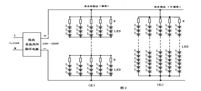
There are three ways to match LED lights: serial, parallel, and parallel.
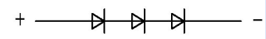
Tandem type:
The LED driver is required to output a higher voltage. When the LED's consistency varies greatly, the voltages distributed across the different LEDs are different, and the brightness of the LED is the same through the same current of each LED.
When one of the LEDs has a bad short circuit quality, if a regulated driver is used, since the output voltage of the driver does not change, the voltage distributed across the remaining LEDs will increase and the driver output current will increase, resulting in easy damage to all remaining LEDs. . If a constant-current LED driver is used, when a certain LED has a bad short circuit, the output current of the driver will remain unchanged and will not affect the operation of all remaining LEDs. When one of the LED's quality is broken, the LEDs connected in series will all be off. The solution is to connect a Zener tube in parallel across each LED. Of course, the turn-on voltage of the Zener tube needs to be higher than the turn-on voltage of the LED, otherwise the LED will not light up.
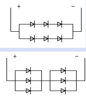
Parallel type:
The LED driver is required to output a large current and the load voltage is low. The voltage distribution across all LEDs is the same. When the LED's consistency is very different, the LED's brightness is different because of the inconsistent current through each LED. The LED with better consistency can be selected and suitable for products with lower power supply voltage.
When the quality of one LED is broken, if the constant voltage LED driver is used, the output current of the driver will be reduced without affecting the normal operation of all remaining LEDs. If a constant-current type LED driver is used, since the output current of the driver remains the same, the remaining LED current distributed will increase, resulting in easy damage to all the LEDs. The solution is to connect the LEDs in parallel as much as possible. When a certain LED is disconnected, the current allocated to the remaining LED is not so large that it will not affect the normal operation of the remaining LEDs. Therefore, when the power LED is connected in parallel, the constant current driver should not be used. When a certain LED has a bad short circuit quality, all the LEDs will not light, but if there are a large number of parallel LEDs, the short-circuited LED current is large enough to short circuit the short-circuited LEDs.

Serial and parallel
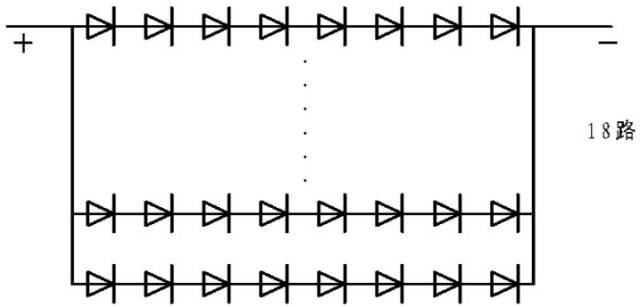
In products that require more LEDs, if all LEDs are connected in series, the LED driver will need to output a higher voltage. If you connect all the LEDs in parallel, you need the LED driver to output a larger current. Connecting all the LEDs in series or in parallel not only limits the amount of LEDs used, but also increases the load current of the parallel LEDs and drives up the cost of the driver. The solution is to use a hybrid approach. The number of series-parallel connected LEDs is evenly distributed. The voltages assigned to a series of LEDs are the same. The currents flowing through the same string and each LED are basically the same, and the brightness of the LEDs is the same. At the same time the current through each string of LEDs is also similar.
When a series LED has a poor quality short circuit, regardless of the use of constant pressure drive or constant current drive, this series of LED is equivalent to a missing LED, the current through this series of LEDs will greatly increase, it is easy to Damage the string of LEDs. After the large current passes through the damaged series of LEDs, due to the large current passing through, a large number of open circuits occur. After disconnecting a string of LEDs, if constant-voltage driving is used, the output current of the driver will be reduced without affecting the normal operation of all remaining LEDs. If a constant-current type LED driver is used, since the output current of the driver remains the same, the remaining LED current distributed will increase, resulting in easy damage to all the LEDs. The solution is to connect the LEDs in parallel as much as possible. When a certain LED is disconnected, the current allocated to the remaining LED is not so large that it will not affect the normal operation of the remaining LEDs.
There is another connection method in the hybrid mode, that is, after the LEDs are evenly distributed, they are grouped in parallel, and then each group is connected in series.
When there is a bad quality LED short circuit, regardless of the use of constant-voltage drive or constant current drive, parallel in this way the LED will be all off, if it is using constant-current LED drive, because the driver output current remains unchanged, except In parallel with this parallel branch of the short-circuit LED, the rest of the LEDs work normally. Assuming that the number of LEDs connected in parallel is large, the drive current of the driver is large, and the current through this short-circuited LED will increase. After the large current passes through this short-circuited LED, it is easy to become a circuit breaker. Because there are many LEDs connected in parallel, the parallel branch of one LED is disconnected and the average distribution current is not large, and it can still work normally. The entire LED lamp, only one LED is not bright.
If constant voltage driving is used, LED quality is short-circuited instantaneously, and the load is relatively low. In parallel, all the LED's will increase in voltage, and the output current of the driver will greatly increase. It is very likely that all LEDs will be damaged at once. Fortunately, only this will be the case. A short-circuit LED burns open and the driver output current will return to normal. Since there are many parallel LEDs, this parallel branch of one LED is disconnected. The average current distribution is small, and the LED can still work normally. Only one LED is off.
Through the above analysis, it can be seen that the driver and load LED series collocation method is very important. The constant-current driving power LED is not suitable for parallel load. Similarly, the constant voltage LED driver is not suitable for series connection.
Simple calculation method in engineering
Example: The rated output power of a power supply is 5W, the output voltage is 12V, the white LED's rated forward voltage is 3.3V, and the dissipated power is 65mW. How many LEDs can be configured?
(1) Calculate the number of LEDs per branch: 3.3V × 3 = 9.9V
65mW ÷ 3.3V = 20mA (12V - 9.9V) ÷ 20mA = 105Ω
(2) Calculate the number of parallel branches: 5W ÷ (65mW × 3 + 20mA × 20mA × 105Ω) = 21
(3) How many LEDs can be connected in total: 21 × 3 = 63 (serial and hybrid)
4: Problems to be noticed when using LED driver
A. LED derating use.
B. Use a linear constant current driver, paying particular attention to its operating differential pressure.
C. The secondary output power supply of the isolated switch constant current driver should not be left unconnected, and the negative electrode should be grounded.
D. For the switching constant current driver, strictly follow: First, connect the LED lamp and then turn on the driver power supply sequence.
We have researched new solutions to the problem of transient current surges and added current-limiting circuits to the output. There are two main implementations.
a. The serial connection method consumes the excess energy inside the current limiting circuit. By blocking the excess energy before the load, it is ensured that the current flowing through the LED lamp load at the instant when the connection switch is closed is within the allowable current range of the LED lamp.
b. The parallel connection method also consumes excess energy in the current limiting circuit. By directing excess energy to the current limiting circuit, it is ensured that the current flowing through the LED lamp is within the safe current range of the LED lamp.
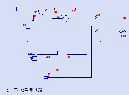
Series current-limiting circuit: It is arranged between the high-frequency filter capacitor (C3) and the constant current loop. The collector-emitter channel of an NPN transistor (Q1) and the collector-emitter channel are included in one horizontal branch. Series limiting resistor (R1). The collector junction bias resistor (R5) is connected between the collector and the base of the NPN transistor (Q1). The base of the NPN transistor (Q2) is connected to the emitter of the NPN transistor (Q1), the collector of the NPN transistor (Q2) is connected to the base of the NPN transistor (Q1), and the NPN transistor (Q2) The emitter is connected to one end of a current limiting resistor (R1). At the same time, the current limiting circuit can be connected in series between the constant current resistor (R2) and the voltage limiting circuit, and can also be connected in series between the voltage limiting circuit and the connection switch (S1), and can also be connected in series with the load and the output polar potential. between.
When the output current is lower than the preset current limit value, the voltage on the current limiting resistor is reduced to 0.7V, the NPN transistor (Q2) is in the off state, and the NPN transistor (Q1) is in the saturated conduction state. The circuit works normally and only adds a small amount of loss to the current limiting resistor (R1) and the NPN transistor (Q1). When the output current is larger than the preset current limit value, a voltage drop higher than 0.7V will occur on the current-limiting resistor. At this time, the NPN-type transistor (Q2) is saturated and turned on, and the NPN-type transistor (Q1) emitter - The equivalent resistance of the collector channel increases, limiting the output current, and effectively protecting the transient over-current phenomenon on the load.
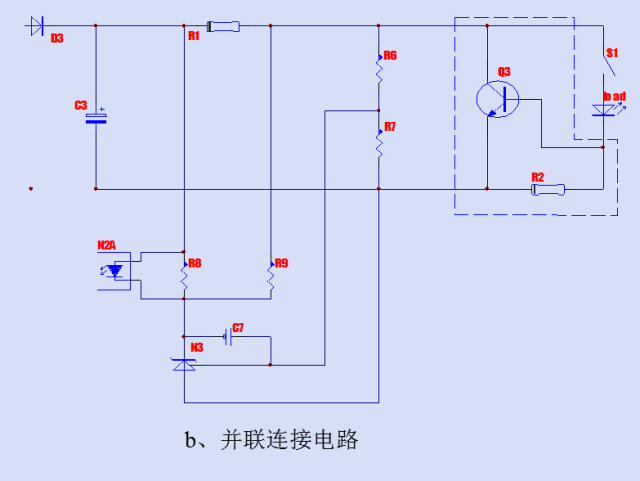
Parallel current-limit circuit: Configured between the output voltage-limiting loop and the load, a collector-emitter channel of an NPN-type transistor (Q3) is connected in parallel to a vertical branch, and the base of the NPN transistor (Q3) is connected to the load. On the negative potential, the current limiting resistor (R2) is connected between the emitter and base of the NPN transistor (Q3). The collector-emitter channel of the NPN transistor (Q3) can be any longitudinal branch after the capacitance.
When the output current value is less than the preset threshold current, the voltage drop across the current limiting resistor (R2) is less than 0.7V, the NPN transistor (Q3) is in the off state, the circuit works normally; when the output current value is greater than the preset value At the threshold current, the voltage drop across the current-limiting resistor is greater than 0.7V. The collector-emitter channel of the NPN-type transistor (Q3) becomes a low-resistance value, allowing most of the current to flow through the collector of the NPN transistor (Q3)— Emitter channels are consumed in the form of heat energy on the collector junction of the NPN transistor (Q3), thereby effectively protecting the load from transient overcurrent phenomena.
Five, LED fluorescent lamp power design experience

Non-isolated buck power supply design method
Non-isolated step-down power supply is a commonly used power supply structure, accounting for almost 90% of the fluorescent lamp power supply. Many people think that the non-isolated power supply is only a step-down type. Whenever it comes to non-isolation, it is thought to be a step-down type, and it is thought that it is not safe for the lamp (the power supply is damaged). In fact, the buck type is not only one, there are two basic structures, namely, boost, and buck-boost, that is, BOOST AND BUCK-BOOST, even if the latter two power supply damage. Does not affect the benefits of LED. The buck-type power supply also has its advantages. It is suitable for 220, but it is not suitable for 110, because 110V is originally low in voltage, even lower in a drop, and the output current is large, the voltage is low, and the efficiency is not too high. Step-down 220V AC, about three hundred volts after rectification and filtering, after the step-down circuit, the voltage is generally reduced to about 150V DC, so that high voltage and low current output can be achieved, and the efficiency can be made higher. MOS is generally used as a switch, and this type of power supply is my experience. It can be done as much as 90 percent. It is also difficult to go up. The reason is very simple, the chip generally has a loss of 0.5W to 1W, but the fluorescent lamp power supply is just about 10W. So it is impossible to go further. Now that power efficiency is very imaginary, many people are blowing, and they actually can't reach it.
Some people often say that 3W's power efficiency is 85%, and it is still isolated. Tell everyone that even if it is frequency hopping mode, the no-load power consumption is the minimum, but also 0.3W, what also output 3W low pressure, can reach 85%, in fact, 70% is very good, anyway, now Many people bragging do not play drafts, you can flicker layman, but now do not understand the power of LED's.
I said that in order to be efficient, first of all do non-isolated, and then output specifications but also high voltage and low current, you can save the conduction loss of power components, so the main loss of such LED power supply, one is the chip's own Loss, this loss is generally a few W to a W like, there is a loss of switching, and switching with MOS can significantly reduce this loss, with transistor switching loss is much larger. So try not to use triodes. There is to do a small power, it is best not to save too much, do not use RCC, because RCC circuit manufacturers generally do not do a good job of quality, its implementation in the chip is also cheap, ordinary switching power supply chip, integrated MOS tube, up to only two yuan Money, no need to save a little bit, RCC only saves material costs, in fact processing and repair costs are higher, but in the end it is not worth the loss.
The basic structure of the buck power supply is to string the inductor and the load into the 300V high voltage. When the switch is switched, the load achieves a voltage lower than 300V. There are many specific circuits and many on the Internet. I do not want to draw a picture again. Now 9910, there are general market constant current ICs are basically implemented using this circuit. But this kind of circuit is when the switch tube breaks down, the entire LED light board is finished, this should be regarded as the worst place. Because when the switch breaks down, the entire 300V voltage is added to the light board. Originally, the light board can only withstand more than one hundred volts. Now it has become three hundred volts. This happens. LED must burn out. So many people say that non-isolated insecurity, in fact, that is buck, just because the vast majority of non-isolated buck, so that non-isolated damage must be bad LED. In fact, the other two basic non-isolated structures, power damage, will not affect the LED.
Step-down power supply should be designed as high voltage and low current, efficiency can be high, to elaborate, why? Because of high voltage and low current, can make the pulse current of the switch tube current larger, so that the peak current is smaller, there is, the inductor The loss is also small, you can know through the circuit structure, the circuit is not convenient to draw, and it is difficult to describe in detail. To sum up, the advantage of the buck power supply is that it is suitable for 220 high-voltage input, so that the power device withstands a small voltage stress, suitable for large current output, such as 100MA current, easier than the latter two ways, efficiency To be high. The efficiency is relatively high, the loss of the inductor is small, but the loss of the switch is larger, because all the power through the load must be transmitted through the switch, but the output power, only part of the inductor, such as 300V input, 120V output Step-down power supply, only 180V part through the inductor, 120V part directly into the load, so that the loss of the inductor is relatively small, but the output power, all through the switch tube conversion.
Decomposition of two constant current control methods
The following is a description of two types of switching power supplies in constant current control mode, resulting in two approaches. These two methods, whether it is the principle, the device application, or the performance difference, are quite large.
First of all, the principle. The first type is represented by current constant-current LED special-purpose ICs, such as the 9910 series and AMC7150. All brands that currently play LED constant-current drive ICs are basically this type of device, and they are called constant-current IC type. But I think this kind of so-called constant-current IC does constant current, but the effect is not very good. The control principle is relatively simple, that is, in the primary circuit of the power supply, a current threshold is set. When the primary MOS is turned on, the current of the inductor is linearly rising, and when it rises to a certain value, When this threshold is reached, the current is turned off and the next cycle is triggered by the trigger circuit. In fact, this kind of constant current should be a kind of current limiting. We know that when the inductance is different, the shape of the primary current is different. Although there is the same peak value, the current average value is different. Therefore, when the power supply is generally mass-produced, the consistency of the constant current size is not well controlled. There is a characteristic of this type of power supply. Generally, the output current is trapezoidal, that is, wave-like current. The output is generally not electrolytically smooth. This is also a problem. If the current peak value is too large, the LED will be affected. If the output stage of the power supply does not have a type of power source that is electrolyzed to smooth the current, this is basically the case. That is to say whether it is this kind of control method, it depends on whether the output is electrolytically filtered. This kind of constant current I have always called it a false constant current, because its essence is a kind of current limit, and it is not the constant current value obtained by comparison of op amps.
The second constant current mode should be called switching power mode. This control method is similar to the constant voltage control method of the switching power supply. Everyone knows to use the TL431 as a constant voltage because it has a 2.5 volt reference inside and then uses a resistor divider. When the output voltage is high, or when it is low, a comparison voltage is generated and amplified to control the PWM signal. Therefore, this control method can control the voltage very accurately. This kind of control method requires a benchmark and also requires an op amp. If the benchmark is adequate, if the op amp amplification is large enough, then it is very accurate. Similarly, to do constant current, you need a constant current reference, an op amp, using resistance overcurrent detection as a signal, and then use this signal to amplify, to control the PWM, but unfortunately it is not very easy to find a very accurate reference signal, Commonly used transistors, this benchmark temperature drift, there is the diode can be about 1V conduction value as a benchmark, this can also be, not high, the best is the op amp plus TL431 when the benchmark, but The circuit is complicated. However, in doing so, the constant current power supply is more accurate than the constant current accuracy. This mode of constant current control, the output must be added electrolytic filter, so the output power supply is smooth DC, not pulsating, pulse can not be sampled. So you have to decide which kind of electrolysis you want to see if you have the output.
The two constant current control modes determine the use of two different types of devices. The first is that the two circuit devices are used differently, the performance is different, and the cost is different. The LED power supply of the constant current type control IC represented by the 9910 series is actually a current limiter, and the control is relatively simple. Strictly speaking, it does not belong to the mainstream mode of switching power supply control. The mainstream mode of switching power supply control must have Benchmarks and op amps. But this kind of IC can only be used for LED, it is very difficult to be used for other things, just because LED has extremely low requirement to ripple. However, because it is only used for LEDs, the price is higher now. Basic is the use of 9910 plus MOS tube production, output electrolysis, generally I see a lot of people is to use the word inductance to do the power conversion inductance. This kind of power supply, the chip data of the general manufacturer has the picture, basically is the step-down type. I don't have much to say. There are more people who are better at it than I am.
The second is represented by me, that is, the constant current driver of the switching power supply control mode. This kind of switch device is based on the ordinary switching power supply chip. There are many such chips, such as PI's TNY series, TOP series, ST's VIPER12, VIPER22, Fairchild's FSD200, etc., even with only triode or MOS tube RCC, etc. can do it. The benefits are low cost and good reliability. Because ordinary switching power supply chips are not only expensive, but they are all classic products that have been used in large quantities. In fact, such ICs generally integrate MOS transistors and are more convenient than 9910 plus MOS. However, the control methods are more complex. It is necessary to add constant-current control devices, use triodes, or operational amplifiers. Magnetic components can be used with I-shaped inductors, but also with high-frequency transformer with air gap.
Questions about this type of power supply and circuit configuration
My opinion is that since the power supply should be built into the lamp and heat is the biggest killer of LED degradation, the heat must be small, that is, the efficiency must be high. Of course there must be an efficient power supply. For the T8-meter-long lamp, it is best not to use a power supply, but to use two, one at each end, to disperse the heat. Concentrate on one place without heating.
The efficiency of the power supply depends mainly on the structure of the circuit and the device used. First of all, the circuit structure, some people also said to isolate the power supply, I think it is absolutely unnecessary, because this kind of thing is originally placed in the lamp body, people simply can not touch. There is no need for isolation because the efficiency of isolated power supplies is lower than non-isolated efficiency. The second is that it is better to output high voltage and low current. Such a power supply can increase efficiency. Now commonly used is the BUCK circuit, the buck circuit. It is best to make the output voltage more than one hundred volts, and the current is set at 100MA. For example, one hundred and twenty drives, preferably three strings, each with forty strings, the voltage is one hundred and thirty volts, and the current is 60MA. .
This kind of power is used a lot, I just think that there is a little bad, if the switch is out of control, the LED will finish playing. Now LEDs are so expensive. I am more optimistic about the boost circuit, the benefits of this circuit, I repeatedly said, one is more efficient than the buck-type, and second, the power is bad, LED lights will not be bad. This will ensure that nothing is lost. If a single power supply is burned, only a few dollars will be lost and an LED fluorescent lamp will be burned, which will cost more than one hundred yuan. So I have been devaluing the boost power supply.
There is, step-up circuit, it is easy to put the PF value high, buck-type on the trouble. The advantages of my absolute booster circuit for LED fluorescent lamps are overwhelmingly stronger than buck-type ones. There is a one-year shortcoming, that is, in the 220V mains input case, the load range is relatively narrow, generally only applicable to 100 to 140 strings or two strings of LEDs, for less than this number, or in the middle, but It is inconvenient to use. But now do LED fluorescent lamps, the general type of 60CM is the use of 100 to 140, one meter two of the kind, is generally used two hundred to two hundred sixty-six, can still be used up. So now LED fluorescent lamps generally use non-isolated buck circuits, and there are no isolation boost circuits.
I am doing switching power supply, originally made adapters, chargers, iron shell switching power supply. Later on as LED power supply, the first was to do some 1W, 3W high-power LED drivers, but later did less. The reason is simple and there is no market. I found that high-power LED constant current power supply, as long as its power exceeds 5W, basically no market, can only be proofing. Because the LED is too expensive. This is also a reminder to my peers who are doing power. This is my experience.
I do not know how many people are slammed into high-power LED, high-power LED thunder, small rain, many of the damage lost in this one. Still a little better in the low-power LED market. However, it is not enough. Nowadays, low-power LED drivers have been used to dissipate most of the country’s power. Constant current switching power supply drives low-power LEDs, which is good, and many people cannot accept their costs.
I love to use transformers because the cost of the inductor is low, but I think it's not capable of carrying loads. In addition, the sense of adjustment is not flexible. So I think the better choice of devices is that ordinary integrated MOS switching power supply chips plus high frequency transformers are the best choices in terms of performance and cost. There is no need to use any constant current ICs. Not useful, expensive.
Reliability, constant current accuracy are all very good, the price is only five dollars, but many people are still too expensive, because they use it and a dollar of resistance and capacity to step down the power supply to compare, of course, the two can not be compared. Inside my switching power supply, there is an integrated MOS switching power supply chip and a transformer. The cost of both is put there, of course, performance is also there. But I believe that in the end the low-power LED constant current driver will eliminate the RC buck power supply. Because consumers will gradually become rational, a resistance-capacity buck power supply to do the lamp, almost no practical value, can only be a decoration and toys, if the LED really into the general lighting field, resistance capacity down Pressure power is simply not up to the task. I can expect that the future situation will be that with the improvement of LED performance and lower prices, power costs will also become a very important part of the cost of LED lighting. Real lamps, resistance and pressure reduction are simply not competent. Resistor-capacitor buck power supply is popular, just a transition, and ultimately the constant current power supply is authentic.
I am still optimistic about low-power LED lamps. Low-power LED lights, the current major decline is too light, the price is not ideal. However, it is still superior to high power for general lighting. I think that low-power LED lamps entering the field of general lighting and energy-saving lamps will be within five years. The introduction of high-power LEDs into general lighting is certainly five years away. So now I focus on the development and production of low-power LEDs. I have noticed that the lamps used for general-purpose lighting in low-power LEDs are mainly LED lamps, LED honeycomb lamps, and LED fluorescent lamps. Especially LED fluorescent lamps, starting from the second half of 2007, many people began to research and development, it can be said that the heat is incredible. Basically, now, eight out of ten people who are looking for me are doing this, so I also started to do LED fluorescent power for a while, so I'll talk about the R&D and production of this type of power supply. Methods and principles. The above is personal experience.
Finally, to distinguish between these two types of power supplies, one of the most important methods is to see if the output has an electrolytic capacitor for filtering.
Regarding the power supply problem—whether it is a current-limiting constant-current control power supply or an op-amp-controlled constant-current power supply, the power supply problem must be solved. That is, when the switching power supply chip works, it needs a relatively stable DC voltage to power its chip. The operating current of the chip varies from one MA to several MAs. One such as the FSD200, NCP1012, and HV9910 is a high-voltage self-fed power supply that is convenient to use. However, high-voltage power feeds cause the IC's heat to rise because the IC has to withstand about 300V DC, with only a small amount of current. Even if a MA, there is a loss of 0.3 watts. The general LED power supply, however, is about ten watts. A loss of a few tenths of a watt or less can pull down the power supply efficiency by several points. There is a typical QX9910. Pull down the power with a resistor, so that the loss is on the resistor, and it must lose about a few tenths of a watt. There is magnetic coupling, that is, using a transformer, add a winding on the main power coil, just like the auxiliary winding of the flyback power supply, so as to avoid losing the zero-watt power. This is one of the reasons why I did not isolate the power supply and use a transformer. In order to avoid losing the power of a few tenths of a watt, the efficiency will be increased to several points.
View of high-power LED fluorescent lamp power supply for high PF LED fluorescent lamp power supply
Personally, there are many times when these practices are really done. Now, first of all, what are the advantages of LED relative to traditional lamps? First, energy saving, second longevity, and then not afraid of switching, right. However, the high PF methods used today all use passive valley filling PF circuits. The original driving method is 48 strings, 6 strings and 24 strings and 12 strings. In this case, the efficiency will be reduced at 220V. About 5 percent, so LED fluorescent power supply, heat is higher, the lamp beads will be affected a little.
There is also a problem, that is, 24 string and 12 together, will make the LED fluorescent lamp beads become difficult to accept the wiring, and bad wiring. In my opinion, the best way is to use 48 strings in a string, which is mainly because of its high efficiency, low heat, and easy wiring and complexity.
What is more, there are still 24 and 12 strings proposed by people. This method is only suitable for isolating power supplies. It is not applicable without isolation. Some people who do not understand the power supply common sense think that their own non-isolated power supply to achieve a constant current output of 600MA cattle X, in fact, he did not himself carefully placed in the lamp, tried, like this is not hot enough to blame.
So, what is the current low-voltage and high-current LED fluorescent lamp power supply?
About appearance
Now LED fluorescent lamp power supply, the manufacturer of the lamp is generally required to be placed in the lamp tube, such as inside the T8 lamp tube. Few parts are external. Do not know why this is the case. In fact, the built-in power supply is hard to do and the performance is not good. But I don't know why so many people demand it. It may be down with the wind. External power supply should be said to be more scientific and more convenient. But I also had to go down with the wind, what the customer wanted, and what I would do. However, it is quite difficult to do a built-in power supply. Because of the external power supply, there is basically no need for shape, and it doesn't matter what shape you want to make. Built-in power supply, can only be made into two kinds, one is the most used, that is put on the light board below, put the light board above, the following is the power, so that the power required to do a very thin, or not installed into. And this can only fall down the components, the line on the power supply is only extended. I don't think this is a good idea. However, everyone generally likes this. I will do it. There is less use, put both ends, that is, on both ends of the lamp, so do something better, the cost is lower. I have also done it, basically these two built-in shapes.
Engine Parts oil tube,Engine Parts water pipe,Engine Parts exhaust pipe,Engine Parts Rubber Pipe
Chongqing LDJM Engine Parts Center , https://www.ckcummins.com