This paper proposes a novel wide-band TEM horn antenna to meet the needs of electromagnetic compatibility (EMC) measurement equipment for broadband antennas. The antenna radiating structure adopts a metal plate with a double-exponentially gradual composite structure with upper and lower symmetry, so that the resonant mode of the antenna is greatly increased, thereby expanding the bandwidth antenna, and then matching the feeding through the balun structure and the coaxial line, thereby reducing the unbalanced feeding at the input end. Strong reflection caused. After optimization of the structure size, the antenna size is 0.356λ & TImes; 0.15λ & TImes; 0.2λ (λ is the lowest operating frequency corresponding to the wavelength). In the frequency range of 0.3 GHz to 10 GHz, the antenna has a voltage standing wave ratio of substantially less than 2, and has a good broadband characteristic of more than 30 octaves. And in the working frequency range, the antenna radiation pattern is stable and the gain is high. The wideband TEM horn antenna proposed in this paper has broadband and good radiation performance, and has broad application prospects in EMC measurement.
I. IntroductionAs a branch of electrical science, Electromagnetic Compatibility (EMC) is a discipline that studies the electromagnetic interference energy that occurs during system transmission, propagation, and reception, and analyzes and resolves the possible adverse effects of these energies. EMC research is a necessary condition for the development of modern electronic technology. In EMC engineering applications, the test frequency range is becoming more and more demanding, so the EMC test expects the antenna's broadband performance to be higher and higher [1]. Antenna structures that meet broadband performance requirements are typically: horn antennas, log-periodic antennas, and biconical antennas.
The horn antenna is widely used in EMC measuring antennas due to its simple structure, high gain and wideband characteristics. Among them, TEM horn antennas have received extensive attention because of their simpler structure and easier excitation [2, 3]. Research on TEM horn antennas has always received attention. M.Kanda studies the effect of impedance loading on the TEM horn antenna, allowing the antenna bandwidth to be stretched by impedance loading [4]. AS Turk et al. increase the bandwidth of TEM horn antennas by loading media on the antenna and using metal plates of unique shape [5]. In this paper, a wideband TEM horn antenna with a radiating part of a symmetric double-graded composite metal plate is proposed. Through CST modeling and simulation optimization, an antenna with good broadband characteristics and high gain performance is finally designed.
Second, the antenna designA. How does the TEM horn antenna work?
A conventional TEM horn antenna generally consists of two planar triangular metal plates and a feed portion having a certain angle. The working principle can be explained by a model of a parallel transmission line. If the planar metal plate is divided into N-segments of sufficiently small size, it is equivalent to N-segment short parallel transmission lines, and each segment is approximately parallel with short metal plates of different widths, as shown in FIG. Then, from the feed end, the input and output impedance of each segment can be expressed by the formula (1) [6]:
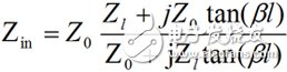
(1)
Zin is the input impedance, Zout is the output impedance, l is the length of the transmission line, Z0 is the characteristic impedance of the transmission line, and β is the wave number of the transmission line.
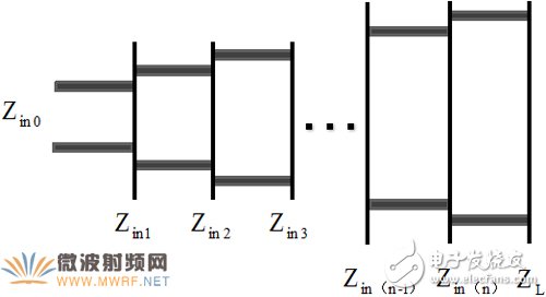
Figure 1. Gradient transfer line model
The impedance of the feeding end is generally 50Ω or 75Ω. Therefore, in order to match the aperture impedance extending to free space by 120πΩ, the planar metal plate of the antenna needs to have a certain gradual structure, that is, the width of the metal plate and the spacing of the metal plates in each segment should extend with distance. And gradually change, so the size of the metal plate and the selection of the elevation angle of the metal plate become an important factor in determining the impedance bandwidth of the antenna.
B. Broadband TEM horn antenna design
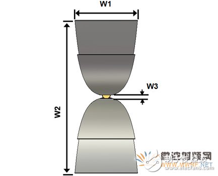
The wideband TEM horn antenna designed in this paper is mainly composed of two parts: coaxial feed and radiating metal plate: the feeding part is a coaxial feeding line, which is matched to the antenna radiating metal plate by the balun structure; the radiating part is a double-gradient composite with upper and lower symmetry Metal plates that broaden the antenna bandwidth by optimizing the design of the gradation structure.
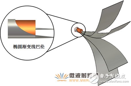
For a TEM horn antenna with a nearly constant impedance within the passband, there is usually a problem of strong reflections caused by unbalanced feeds at the input. In order to avoid and reduce these reflections, the impedance transformation should be implemented at the input of the TEM horn antenna through the balun structure to match the impedance of the antenna and the feed line in the passband. The elliptical gradient line balun structure of the antenna design in this paper is shown in Fig. 2. (a). The inner core of the coaxial line is fed into the upper metal plate of the antenna through the trapezoidal gradient structure, and the outer skin of the coaxial line is transformed by the elliptical gradient line structure. Go to the metal plate feed end of the lower half of the antenna.
The gradual structure of the radiating metal surface makes the impedance of the TEM horn antenna smoothly transition to the input port. In this paper, two kinds of composite structural metal plates with inconsistent gradual structure are adopted, which greatly increases the resonance mode of the antenna and expands the bandwidth. At the same time, according to the Yagi antenna principle, the slowly gradual metal plate can provide a director with a relatively gradual strong metal plate. Similarly, the metal plate with a relatively gradual slow gradient is equivalent to a reflector, thereby improving the TEM horn antenna. Orientation.
The broadband TEM horn antenna of this paper is modeled in the electromagnetic simulation software CST. As shown in Fig. 2, the metal plate material is set to PEC, and the feed port is a wave port. The contour curve of the graded metal plate can be expressed by the formula (2). Where h represents the height of the radiating metal plate from the centerline of the antenna, and W represents the width of the radiating metal plate, both of which vary with the length of the antenna extension. t and t1 are the lengths of the radiating metal plate extending to the caliber surface, and A, B, C, D, and t are the contour curve parameters of the gradually slowing metal plate, and A1, B1, C1, D1, and t1 are the contour curves of the progressively strong metal plate. parameter. In this design, the height curve shows an exponential increase, and the width curve shows a linear increase. In order to obtain the appropriate antenna impedance bandwidth and gain, the antenna structure size is simulated and optimized, and the main parameters of the antenna structure are shown in Table 1.
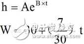 (2)
(2)
0mm≤t≤200mm, 0mm≤t1≤150mm
Table 1:
AA1BB1CC1
550.0150.0241515
DD1W1W2W3W4
0.270.4150mm365mm10mm20mm
(a) Antenna stereogram
(b) Antenna front view (left) and side view (right)
Figure 2. Antenna structure diagram
Third, the simulation results analysisAfter optimizing the antenna parameters by CST simulation software, the voltage standing wave ratio (VSWR) of the antenna is shown in Figure 3. It can be seen that the antenna has a VSWR of 2 in the entire frequency range of 0.3 GHz to 10 GHz, and the octave reaches 33.3. The reason why the antenna has such a wide impedance bandwidth is that the exponentially gradual metal plate structure makes the feed port impedance smoothly match the impedance of the horn to the horn surface area, so that the electromagnetic wave can pass through the free space well. At the same time, the composite gradation structure also increases the resonance mode of the TEM horn antenna. For the input port, the antenna input impedance is approximately constant due to the gradual matching structure of the antenna in the operating band.
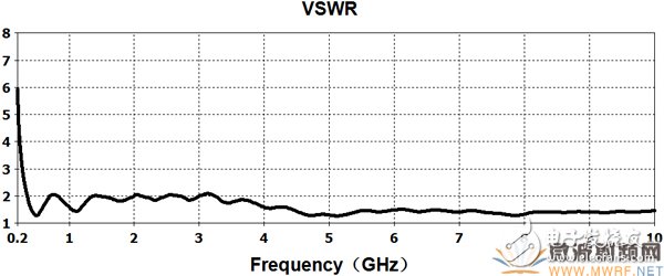
Figure 3. Return loss graph
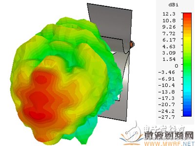
The stereo radiation pattern of the wideband TEM horn antenna at 2.5 GHz, 5 GHz, and 7.5 GHz is shown in Fig. 4. The antenna exhibits stable radiation pattern performance. At each simulation frequency, the gain can reach 11dBi and the back-lobe level is low. And basically as the operating frequency increases, the antenna gain is higher. Conventional TEM horn antennas are prone to distortion of the pattern due to unbalanced feed problems. In this paper, the antenna passes through the elliptical gradient line balun structure, so that the radiated part of the antenna is balanced and fed, which weakens this effect. At the same time, the composite metal plate structure further improves the orientation of the antenna.
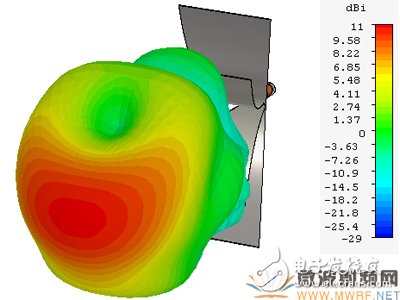
(a) 2.5 GHz
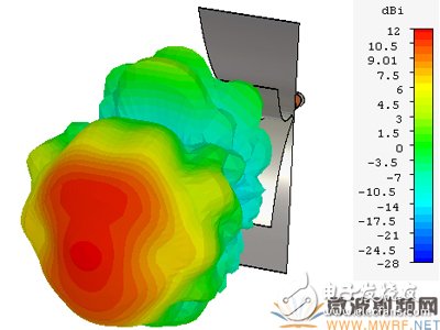
(b) 5 GHz
(c) 7.5 GHz
Figure 4 antenna stereo radiation pattern
Fourth, summaryIn this paper, according to the requirements of EMC measurement equipment for ultra-wideband antennas, a novel wideband TEM horn antenna is proposed. The radiating portion of the antenna has an exponentially graded structure, and the aperture surface has a size of about 365 mm & TImes; 150 mm and a radial length of 200 mm. Through the elliptical line gradient balun structure and the exponentially graded structure of the radiating metal plate, the impedance of the antenna feed end can be smoothly matched with the free space impedance, and the resonance mode is improved due to the recombination of the double gradient structure, so that the antenna operates at a frequency of 0.3 GHz to 10 GHz. The voltage standing wave ratio in the range is less than 2, the fractional bandwidth is greater than 18.8%, and the octave is greater than 30. At the same time, the four metal plate structure of the antenna improves the gain and pattern stability of the antenna. The final antenna has high gain characteristics, and the radiation pattern is stable at each frequency point.
Cast iron Fire pit size : diameter 60cm 80cm to 100cm .
Thickness of cast iron Fire pit/Fire bowl : 1.2mm
Packing of cast iron Fire pit /Fire bowl : plybag,wooden case or carton
Packing quantity of Fire pit/Fire bowl : 6pcs/ctn ,or put into wooden case .
Fire pit also named Fire bowl ,fire-pit .
Fire pit size: diameter 60cm 80cm to 100cm .
Thickness of cast iron Fire pit/fire bowl : 1.2mm
Packing of cast iron Fire pit/Fire bowl : plybag,wooden case or carton
Packing quantity of Fire pit/Fire bowl : 6pcs/ctn ,or put into wooden case .
Outdoor Fire Pit,Metal Fire Pit,Fire Bowl,Bowl Fire Pit
BAODING JIMAOTONG IMPORT AND EXPORT CO., LTD , https://www.chinagroundscrew.com