Metamaterial refers to an artificial composite material or structure in which natural materials are processed by artificial means and have extraordinary physical properties not possessed by natural materials.
Generally, the electromagnetic properties of any one of the media can be described by two macroscopic physical quantities: dielectric constant ε and magnetic permeability μ. The dielectric constant and magnetic permeability of free space are represented by ε0 and μ0, respectively (ε0 and μ0 are greater than zero), and for general materials: ε = ε0εr, μ = μ0μr, where εr represents relative dielectric constant and μr represents relative magnetic The conductivity, the refractive index of the medium is defined as ![]() . According to the different values ​​of ε and μ, the material space can be divided into four quadrants, as shown in Figure 1. The first quadrant (ε>0, μ>0) characterizes the general material in nature, also known as the right-hand material. When the electromagnetic wave propagates in this material, the electric field, magnetic field and wave vector direction satisfy the right-handed spiral relationship, energy and The phase propagation direction is the same (forward wave); the second quadrant (ε<0, μ>0) characterizes the plasma material, and the fourth quadrant (ε>0, μ<0) characterizes the ferrite material. Since the phase constant is imaginary when the electromagnetic wave propagates in the two media, both materials have only evanescent waves; the third quadrant (ε<0, μ<0) represents the left-hand material, and the electromagnetic wave is in this material. In the middle propagation, the electric field, the magnetic field and the wave vector direction satisfy the left-handed spiral relationship, and the energy and phase propagation directions are opposite (backward wave).
. According to the different values ​​of ε and μ, the material space can be divided into four quadrants, as shown in Figure 1. The first quadrant (ε>0, μ>0) characterizes the general material in nature, also known as the right-hand material. When the electromagnetic wave propagates in this material, the electric field, magnetic field and wave vector direction satisfy the right-handed spiral relationship, energy and The phase propagation direction is the same (forward wave); the second quadrant (ε<0, μ>0) characterizes the plasma material, and the fourth quadrant (ε>0, μ<0) characterizes the ferrite material. Since the phase constant is imaginary when the electromagnetic wave propagates in the two media, both materials have only evanescent waves; the third quadrant (ε<0, μ<0) represents the left-hand material, and the electromagnetic wave is in this material. In the middle propagation, the electric field, the magnetic field and the wave vector direction satisfy the left-handed spiral relationship, and the energy and phase propagation directions are opposite (backward wave).
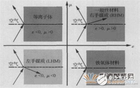
Figure 1 Material space for ε and μ construction
The general medium in nature only accounts for a part of the first quadrant. Plasma and ferrite also account for only a few of the second and fourth quadrants, while the third quadrant (ε<0, μ< The left-handed material in 0) does not exist in nature. That is to say, most of the media needs to be obtained by the "hypermaterial" method, including all left-handed materials and most right-handed materials, but the narrow metamaterials usually refer to left-handed materials.
Second, the research process of metamaterialsSince the beginning of the 20th century, some scholars have studied the transmission properties of negative dielectric constant media and backward waves. In 1968, Soviet scientist VGVeselago systematically analyzed the characteristics of hypothetical media with negative dielectric constant and magnetic permeability. And proposed the concept of left-handed materials. His research shows that the left-handed material not only has a negative refractive index (as shown in Figure 1, the incident wave and the refracted wave are on the same side of the normal line) and the characteristics of the propagating backward wave, but also has an inverse Doppler effect and a reverse-cutting Singular characteristics such as radiation and sub-wavelength diffraction. However, in the next 30 years, due to lack of experimental verification, the left-hand material has not been paid attention to. Until 1996, British scientist Pendry constructed an artificial medium composed of a periodic array of thin metal rods to achieve a negative equivalent dielectric constant. Then, in 1999, an artificial medium composed of a metal resonant ring array was constructed to achieve a negative equivalent magnetic permeability. Later, in 2001, the research team led by Professor Smith of Duke University in the United States used Pendry's theoretical model to regularly arrange the two sides of the fine metal wire and the metal resonant ring structure regularly to achieve the equivalent dielectric constant and The left-handed material with magnetic permeability at the same time is negative, as shown in Fig. 2, and the existence of the left-handed material is verified by the prism experiment. After that, the theoretical research, structural design and application research on the left-handed material quickly become the physics and electromagnetic field. Research hotspots. However, due to the large loss of the left hand material and the narrow bandwidth, it is difficult to apply.

Figure 2 Structure of the left hand material
At the same time, in 2002, three research groups led by Eleftheriades, Oliner, and Caloz-Itoh proposed a transmission line model of the left-hand material almost simultaneously. As we all know, the equivalent circuit model of the traditional lossless transmission line (right-hand transmission line) can be composed of a low-pass LC network. The unit model is shown in Figure 3(a). If we replace the low-pass circuit structure with the high-pass structure, The series inductor is replaced by a series capacitor, and the shunt capacitor is replaced by a shunt inductor. As shown in Fig. 3(b), an equivalent circuit model of a left-hand transmission line capable of transmitting a backward wave is constructed. In practice, pure left-hand transmission lines cannot be realized due to parasitic effects. Only a transmission line that exhibits "left-hand characteristics" in a certain frequency range and "right-hand characteristics" in other frequency ranges can be designed. Called "Composite Right / Left - Handed Transmission Line" (CRLH TL), the equivalent circuit model unit is shown in Figure 3 (c). Compared with the left-handed material composed of a metal resonant structure, this metamaterial has the advantages of low loss, wide bandwidth, and singular dispersion characteristics, enabling miniaturization of passive components and continuous scanning of leaky antennas from backfire to endfire. And many applications have been made to realize the miniaturization of the resonant antenna.
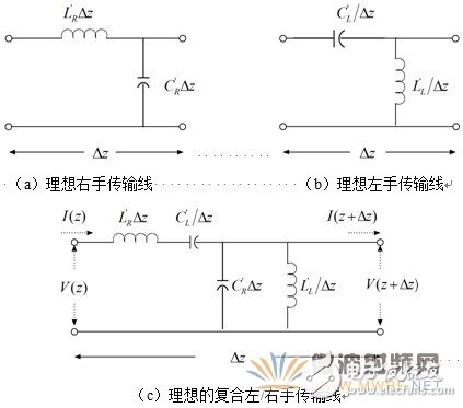
Figure 3 Equivalent circuit model units of various ideal transmission lines Because of the large loss and narrow bandwidth of left-handed materials, scientists are looking for other properties of metamaterials other than negative refraction. In 2005, the super-materials ushered in the second revolution. Researchers found that the gradient-index medium can achieve electromagnetic wave deflection. In 2006, the gradient hyper-media was used to realize the electromagnetic wave invisibility, and the electromagnetic hyper-media could be used to control the electromagnetic wave propagation direction. Since then, metamaterials have not only included left-handed materials, but they have a broader meaning. It does not have to have a dielectric constant less than zero and does not necessarily have a permeability less than zero. At present, several supermaterials are studied: left-handed materials, composite left/right hand transmission lines, photonic crystals, invisible clothes, electromagnetic black holes, and the like.
Third, the application of metamaterials in the antenna3.1. Application of super medium in high performance electric small antenna
3.1.1. Hypermedia-loaded antenna based on spatial matching principle
Generally, the small antenna has a small radiation resistance, a large reactance, and a serious mismatch with the source impedance, and the radiation efficiency of the antenna is low. Since 2003, RW Ziolkowski has conducted in-depth research and analysis on electric small dipole antennas and loop antennas based on hyper-medium loading, and proposed the concept of spatial matching. The results show that the ultra-dielectric layer is loaded in the near field of the small antenna (as shown in Fig. 4). With proper design, the hyper-media layer can largely offset the reactance of the small antenna, thus improving the radiation efficiency of the antenna. At the same time, under the excitation of the antenna body, the loaded hyper-media structure becomes the parasitic radiation element of the antenna through spatial coupling, which further improves the efficiency and gain of the antenna.
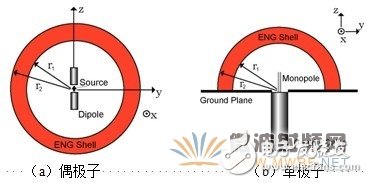
Figure 4: Small antenna with ultra-medium loading
The principle of spatial matching based on hyper-medium loading can be simply illustrated by Figure 5: Taking a dipole antenna as an example, the whole antenna and its near-field region (free space) can be regarded as an electric small dipole, equivalent. Is a capacitor; the metamaterial layer wrapped around the antenna (consisting of the left-hand material or the single-negative material ENG of ε<0) can be considered as another electric dipole under the excitation of the antenna, but due to the introduction of the meta-material layer The electrical constant is negative, the reactance is inductive rather than capacitive, and the metamaterial layer is equivalent to an inductance. Therefore, the entire low dielectric loaded small antenna system is equivalent to an LC resonator, which is equivalent to the antenna and A matching network is added between the spaces to reduce or even cancel the reactance of the antennas to improve the antenna radiation efficiency.
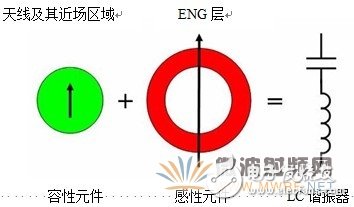
Figure 5 Schematic diagram of spatial matching principle of hypermedia loading
Bell Labs designed a monolithic monopole antenna based on the principle of spatial matching (Figure 6), reducing the size of the monopole to λ/50. ![]() The radiation efficiency also reached 61%.
The radiation efficiency also reached 61%.
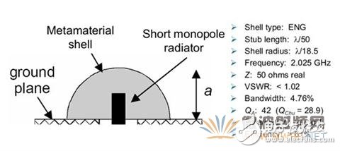
Figure 6: A multi-media loaded monopole antenna designed by Bell Labs
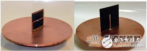
3.1.2 Near-field resonant parasiTIc antenna (NFRP antenna)
The design of the NFRP antenna is actually derived from the space matching principle of the hyper-medium loading. The difference is that the NFRP antenna does not need to load the super-media layer to cover the entire radiator. It only needs to load some hyper-media structures in the near-field of the antenna. By designing the structure, size and position of the metamaterial, it is also possible to cancel the antenna reactance and match the impedance of the antenna with the source impedance. The equivalent model and matching principle of the NFRP antenna are shown in Figure 7. Several NFRP antennas designed by RW Ziolkowski et al. are shown in Figures 8-10.
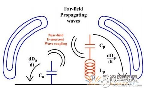
Figure 7 NFRP antenna works
model
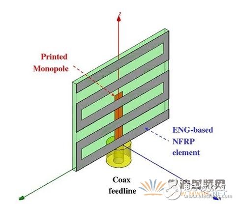
Z-type ENG super medium (reverse) printed monopole (front)
Figure 8 NFRP monopole antenna based on Z-type ENG loading
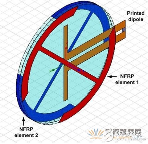
Figure 9 GPS L1 NFRP circularly polarized antenna
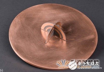
Figure 10 Dual-frequency GPSL1/L2 NFRP circularly polarized antenna 3.2, composite left/right hand transmission line in the antenna
3.2.1. Electronically controlled scanning composite left/right hand (CRLH) leaky wave antenna
Since 2002, composite left/right hand transmission lines have been introduced into the design of antennas, and L. Liu, C. Caloz, T. Itoh, and George V. Eleftheriades have used CRLH transmission lines based on microstrip lines and strip lines. The leaky wave antenna has undergone extensive research. The CRLH leaky wave antenna mainly utilizes the dispersion characteristic of the phase constant of the CRLH transmission line under continuous balance from a negative value to a positive value, and realizes lateral beam radiation and continuous scanning from back to end. The traditional leaky wave antenna controls the radiation direction of the main beam by the change of the frequency. For the leaky wave antenna formed by the CRLH transmission line, only the varactor diode is properly loaded on the antenna, and the capacitance value of the varactor is changed by voltage control. (ie changing the LC parameters of the transmission line), the phase constant β of the CRLH transmission line can be easily changed. ![]() , thereby changing the radiation angle of the main beam of the antenna
, thereby changing the radiation angle of the main beam of the antenna ![]() Θm(θm≈arsin(β/k0)), which is the electronically controlled leaky wave antenna implemented by the CRLH transmission line (as shown in Figure 11). In 2009, Tetsuya Ueda et al. proposed a method of loading ferrite materials to implement a non-reciprocal CRLH transmission line and applying it to a leaky wave antenna. C. Caloz et al. also proposed loading a ferrite material in a rectangular waveguide and designing a waveguide structure CRLH transmission line leakage wave antenna.
Θm(θm≈arsin(β/k0)), which is the electronically controlled leaky wave antenna implemented by the CRLH transmission line (as shown in Figure 11). In 2009, Tetsuya Ueda et al. proposed a method of loading ferrite materials to implement a non-reciprocal CRLH transmission line and applying it to a leaky wave antenna. C. Caloz et al. also proposed loading a ferrite material in a rectangular waveguide and designing a waveguide structure CRLH transmission line leakage wave antenna.
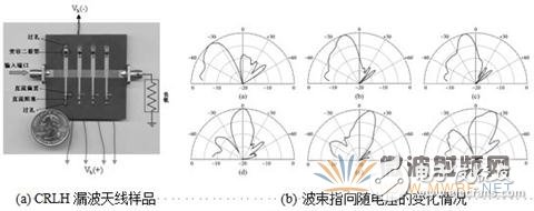
Figure 11 Electronically controlled scanning CRLH leaky wave antenna
3.2.2, CRLH zero-order resonant small antenna
The inversion and inverse group velocity phenomena of CRLH transmission lines are very useful in resonant antennas. The use of CRLH transmission line with negative order, zero-order resonance characteristics can not only greatly reduce the size of the antenna, but also improve the performance of the resonant antenna, which has superior singular characteristics than the traditional microstrip antenna. As shown in Figure 12, a zero-order resonant antenna realized by a CRLH transmission line structure resonator without a via (the CRLH transmission line structure is realized by an interdigital capacitor and a broken line inductor), and the resonant frequency of the antenna is only related to the size of the capacitor and the inductor, and The physical size of the structure is independent, which means that the size of the antenna can be arbitrarily small, and the limit of the minimum size is the minimum size of the LC value component required by the fabrication technique. Figure 13 is a comparison of the size of a CRLH transmission line zero-order resonant antenna sample with a working frequency of 4.88 GHz and a conventional patch antenna sample with a working frequency of 4.9 GHz. Compared with a half-wavelength patch antenna, the size of the zero-order resonant antenna is reduced. About 75%.
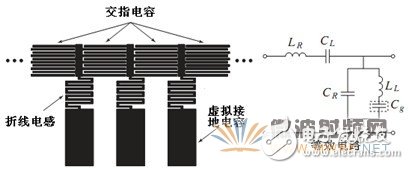
Figure 12 Structure of the zero-order resonant antenna and its equivalent circuit
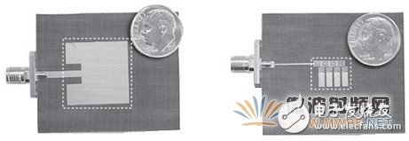
Figure 13 Size comparison of microstrip resonant antenna samples
3.3. Application of zero-index super-materials in high directional antennas
According to Snell's law, when electromagnetic waves are obliquely incident on the interface between the hypermedium and the free space, there are: n1sinθ1=n2sinθ2
Where θ1 and θ2 are the incident angle and the refraction angle of the electromagnetic wave, respectively, n1 is the refractive index of the free space, and n2 is the refractive index of the super medium. Assuming that the hyper-media is a left-handed material with ε<0, μ<0, then the refracted wave will be on the same side of the normal as the incident wave, as shown in FIG.
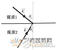
Figure 14 Transmission relationship of electromagnetic waves at the interface of two different media
(Media 1 is free space and Medium 2 is left-hand material)
Assuming that the equivalent dielectric constant (ε = ε0 εr) or magnetic permeability (μ = μ0 μr) of the super medium tends to zero, and its refractive index n2 also approaches zero, this material is called a zero-refractive-index metamaterial ( Zero – index metamarerial, referred to as ZIM). When an electromagnetic wave is incident on the interface between the ZIM and the free space, no matter what incident angle the electromagnetic wave is incident on the ZIM, the exit surface can be launched into the free space in a direction parallel to the normal, and the originally radiated electromagnetic wave Arranged into an approximately parallel wave that is closer to the direction of the normal to the interface, which functions as an energy convergence, as shown in Figure 15. In the near field of the antenna, it cannot be completely summarized by reflection and refraction. At the same time, it can be considered that when the frequency of the electromagnetic wave is close to the equivalent plasma frequency of the ZIM structure, a strong resonance occurs, and the electromagnetic field has strong field coupling in the structure. At this point the ZIM can be coupled into an array of radiation sources that produce approximately parallel wave radiation. By using the ZIM feature, it covers the antenna array and can effectively converge electromagnetic waves, thereby improving the directivity and gain of the array antenna (as shown in Figure 16), reducing the number of antenna elements at the same gain. This is of great significance for the miniaturization of array antennas.
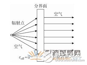
Figure 15 Schematic diagram of electromagnetic energy generated by the ZIM layer
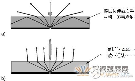
Figure 16 Overlaying the traditional right-hand material over the antenna versus ZIM beamwidth
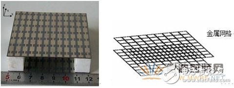
Figure 17 Several super-media structures with zero refractive index
3.4. Application of metamaterials in MIMO antennas
The introduction of metamaterials in MIMO antennas is primarily intended to reduce (or even eliminate) the effects of mutual coupling between the antennas.
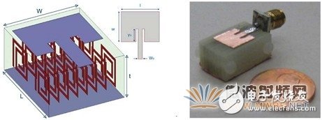
Figure 18 MIMO antenna using metamaterial as the substrate
Baccarelli theoretically analyzed the scattering equation of the substrate and proposed the conditions for suppressing the surface wave TE mode and TM mode with the left-handed material as the antenna substrate. He pointed out that using the left-hand material as the antenna substrate can reduce the edge scattering of the antenna and improve the radiation efficiency of the antenna. When the left-hand material and the right-hand material are combined as the antenna substrate, the antenna edge radiation can be suppressed, the interference between the antenna elements can be reduced, and the antenna can be improved. Directionality. A microstrip patch antenna using a metamaterial as a substrate is shown in FIG.
Withstand high voltage up to 750V (IEC/EN standard)
UL 94V-2 or UL 94V-0 flame retardant housing
Anti-falling screws
Optional wire protection
1~12 poles, dividable as requested
Maximum wiring capacity of 16 mm2
30 amp Terminal Blocks,high quality Barrier Terminal Connector,high performance Polypropylene Terminal Block,Polyamide66 Terminal Blocks,BELEKS T16 series connector terminal
Jiangmen Krealux Electrical Appliances Co.,Ltd. , https://www.krealux-online.com