0 Preface
Today, the wireless communication industry is developing rapidly, and handheld computers, laptop computers and mobile phones have become a necessity for people's lives. At the same time, communication systems also require wide frequency bands to achieve high rates of wireless transmission and reception of multimedia information. Because slot antennas with microstrip feeding have a wide impedance bandwidth and a simple structure, as well as ease of processing and low cost, this type of antenna is also being widely used in various wireless transmission equipment.
In fact, although people have conducted extensive and in-depth research on slot antennas fed by microstrip. However, how to simultaneously achieve the miniaturization and broadband characteristics of the antenna is still a difficult task. At present, researchers have proposed two types of microstrip open slot structures (L-shaped and inverted T-shaped), these structures can achieve broadband characteristics and reduce the size of the antenna.
This paper proposes a new design method for the slot antenna. The antenna uses FR4 dielectric board and uses 50Ω impedance matching microstrip feed. Since this solution places the floor on one side of the dielectric board, the microstrip feeder is placed on the other side of the dielectric board. Therefore, by coupling the open slot through the microstrip line, the broadband characteristics of the antenna can be achieved.
1 Antenna size design
Figure 1 shows the specific structural dimensions of the antenna. The antenna is fabricated on a FR4 dielectric board with a thickness of 0.8 mm and a dielectric constant of 4.4. The size of the dielectric board is 27 mm × 30 mm. During the design, the opening gap can be opened on the floor, and the position of the gap should make the whole floor asymmetry. The microstrip feeder is located on the other side of the dielectric board. In this way, the broadband characteristics of the entire small antenna can be achieved by coupling between the 50 Ω impedance-matched microstrip feeder and the open slot on the back.

2 Antenna structure
The opening slot of the antenna has a rectangular structure, and the length L and the width W are the main parameters. The slot length L determines the resonance mode in the lower frequency band, and the resonance mode in the higher frequency band is generated by the slot width W excitation. In this way, by properly selecting the size of the opening slit, that is, the length and width of the slit, the two modes can be well coupled to achieve a wider impedance bandwidth. At the same time, you can also adjust the position of the opening slot on the floor, or adjust the position of the microstrip feeder, so that the antenna has better impedance matching characteristics.
3 Performance parameters
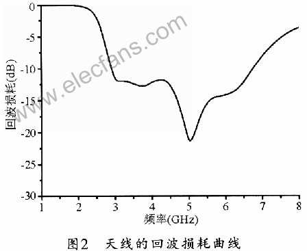
Figure 2 shows the return loss curve obtained by the antenna simulation. The working frequency band of the antenna is 2.89 ~ 6.74 GHz, the impedance bandwidth is about 80.2%, and the return loss is less than -10 dB. Table 1 lists the working frequency bands corresponding to different sized floors of the antenna when L2 is unchanged. Figure 3 shows the gain curve of the antenna. It can be seen that the gain of the antenna in the entire operating band changes less than 3 dB. At the same time, the radiation direction of the antenna is also acceptable for wireless transmission equipment.

4 Conclusion
This article gives a design method of a miniaturized broadband antenna. The antenna places the floor on one side of the dielectric board and the microstrip feeder on the other side. The broadband characteristics of the antenna can be achieved through the coupling between the microstrip feeder and the open slot. The antenna size is 27mm × 30mm × 0.8 mm, and the impedance bandwidth is 80.2%. The small structure and wide frequency characteristics of the antenna make it very suitable for use in mobile terminal equipment.
At the end of the 1940s, the first semiconductor triode was born in the world. With its characteristics of small size, light weight, power saving, and long life, it was quickly used by various countries and replaced electronic tubes in a large range. In the late 1950s, the first integrated circuit appeared in the world. It integrated many electronic components such as transistors on a silicon chip, making electronic products smaller. Integrated circuits have rapidly developed from small-scale integrated circuits to large-scale integrated circuits and ultra-large-scale integrated circuits, thereby enabling electronic products to develop in the direction of high efficiency, low consumption, high accuracy, high stability, and intelligence.
Digital Home Appliances Circuit Board
Appliances Printed Circuit Board,Automative Circuit Board,Digital Home Appliances Pcb,Digital Home Appliances Circuit Board
Chuangying Electronics Co.,Ltd , https://www.cwpcb.com