The PLM1000 appears in this market context in a timely manner, providing a high-definition signal interface for ordinary CRT TVs, enabling the TV to watch HD programs without updating. This method of increasing functionality at low cost is very in line with national conditions and adapts to the needs of the majority of low-end users.
This article refers to the address: http://
The main features of the PLM1000 chip
The PLM1000 series of high definition television image processing chips is an analog/digital hybrid processing chip designed for ordinary CRT TVs using a 0.18 micron CMOS process. It uses 10bit signal quantization, original input signal format automatic detection and high quality image processing solutions.
The PLM1000 chip digitizes the input analog TV signal, performs digital signal processing, and finally restores the digital signal to an analog TV signal and outputs it to an analog TV. It supports most high-definition video signals such as 480P, 576P, 720P, 1080i, 1080P and VGA signals, and supports 4:3, 16:9 and configurable zoom processing; without external memory, all operations Complete on-chip, saving cost; support brightness, chrominance, saturation, chroma space conversion and RGB conversion.
The main features of the chip are as follows:
* 1080P/1080i/720P/480P/ 576P/480i/576i component input, 480i/576i component output;
* VGA input;
* Analog input and analog output;
* When the input signal field frequency is 50Hz, the output signal is 576i; when the input signal field frequency is 60Hz, the output signal is 480i;
* When the input signal is 576i or 480i, the input signal is directly output;
* The input signal is compatible with Macrovision;
* The analog-to-digital converter and digital-to-analog converter used at the input and output are both 10-bit converters, which provides 12dB higher signal-to-noise ratio than traditional 8-bit converters;
* Image enhancements;
* Image presentation function;
* No external memory saves system cost;
* Provide external universal two-wire serial bus control interface, the software is simple;
* The output is equivalent to the image quality of the analog CRT interlaced TV when the DVD signal is input;
* SDIP64 or LQFP64 package, can be directly installed on the motherboard of the TV;
* 3.3V/1.8V power supply.
Application System Design Based on PLM1000
Figure 1 is a block diagram of the application system based on the PLM1000 chip.
  
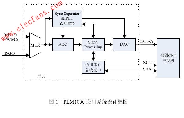
From the high-definition video image outputted by the player such as EVD/DVD to the PLM1000 video input terminal, after processing by the PLM1000, the standard-definition component image 480i or 576i is output to the component input end of the ordinary CRT television set, and the subsequent processing is exactly the same as that of the ordinary CRT television set. .
The PLM1000 is mainly composed of a video MUX module, a synchronous splitter, a PLL and a clamp module, three 10-bit high-speed ADCs, a Signal Processing module, three 10-bit high-speed DACs, and a universal serial bus interface module. These modules will be introduced separately below. How it works.
(1) Video MUX module
The PLM1000 supports two channels of video simultaneous input: Y/Pb/Pr or Y/Cb/Cr and R/G/B. The video MUX module selects one channel of video and inputs it to the ADC. The luminance signal Y is simultaneously input to the sync separator module.
(2) Synchronous splitter, PLL and Clamp module
The input luminance signal Y is separated from the composite synchronization, horizontal synchronization, and vertical synchronization required by the subsequent processing module by the synchronous separator module, and the input signal is detected according to the separated signals according to different formats. The format of the signal. The detected format is passed to the register control module, which configures the corresponding register value to the processing module based on the detected mode selection.
The internal analog phase-locked loop PLL can generate pixel clocks based on the line sync frequency, and provide different clock signals according to different signals. In order to preserve more image details, the image still retains most of the details after processing. The sampling clock is used to sample the output of the ADC. Taking 480P as an example, the standard definition sampling rate is 27MHz, and the row effective point is 858 points. According to the oversampling, we use the 75.6MHz sampling clock, and the number of sampling points reaches 2400 points. The details of the image are added.
The transmission of video signals is generally AC-coupled. In order to recover the DC components in the video signal and eliminate low-frequency interference such as superimposed interference in the video signal, the input signal must be clamped. The clamp circuit receives the accurate clamp information input by the Signal Processing module and clamps the input signal to a fixed DC level.
(3) 3-channel 10-bit high speed ADC
The 3-channel high-speed ADC converts the input high-definition analog video signal into a digital signal. The 10-bit quantization, which is only used by professional-grade video processors, guarantees the sampling detail and accuracy. Compared with the traditional 8-bit ADC, the signal-to-noise ratio is improved by 12dB. In the subsequent signal processing and the final digital-to-analog conversion, 10 bit processing is used.
(4) Signal Processing module
Each of the three 10-bit data quantized by the ADC enters the Signal Processing module. At the heart of the module is a high-performance video scaling module that produces HD video signals at different scaling ratios. It is divided into two parts: a horizontal scaling unit and a vertical scaling unit. Connecting the horizontal and vertical scaling units is a single-port RAM that, compared to dual-port RAM, reduces the chip area because it adds a small portion of the control logic, but because the single-port RAM is much smaller than the dual-port RAM area.
Traditional TV is where the user manually adjusts the image parameters according to his or her preference, but if the program content changes, such as playing a program with a particularly poor contrast, the user needs to adjust again. The PLM1000 includes an automatic image enhancement function, which automatically modifies the low frequency signal of the image according to the video image content, and enhances the high frequency signal of the image, thereby automatically adjusting the image parameters and enhancing the visual effect of the image.
The module performs both chromaticity space conversion, YUV to RGB, and brightness, chrominance, and saturation adjustment.
(5) 3-channel 10-bit high speed DAC
The high-speed DAC module function converts the processed digital signal into an analog signal input to an analog TV. The PLM1000's DAC clock is twice the defined output clock, taking into account the convenience of the manufacturer for subsequent analog filtering and eliminating the refraction effects in the frequency domain.
(6) Universal serial bus interface.
The conversion chip and the external interface are a general-purpose two-wire serial bus protocol, which can be used to configure the register values ​​that the PLM1000 needs to change.
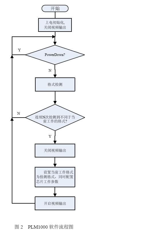
The PLM1000 software flow is shown in Figure 2:
  
Â
After power-on, the CPU of the TV performs power-on initialization on the PLM1000 chip and performs the necessary register configuration. At the same time, in order to avoid the display of uncertain information during the initialization of the power-on, the PLM1000 turns off the video output. To save power, the PLM1000 supports Standby Power Down mode (Power Down). In this mode, the PLM1000 chip and its peripheral circuits consume less than 2mA. After the power-on initialization is completed, the CPU reads the internal automatic format detection result of the PLM1000 chip, and judges the current input signal format according to a preset rule. If the continuous N times detection result is different from the current signal format, the current detection result is set to a new chip format, the CPU turns off the PLM1000 chip video output, and the corresponding working parameters are configured on the chip to enable the video output; if different, the original format is maintained. , that is, the PLM1000 works in the original format.
PLM1000 Application Note
As a highly integrated HDTV image processing chip, the PLM1000 can operate with only a small number of external circuit components and 3.3V/1.8V power supply. It uses a universal serial bus that can be directly connected to the TV's CPU. TV manufacturers only need to add a few programs to the existing program to complete the PLM1000 chip configuration.
The PLM1000 is available in two packages: SDIP64 and LQFP64.
The SDIP64 package chip can be directly installed on the main board of the TV. Therefore, the TV manufacturer does not have to change the original single-layer circuit board production line, and only needs to increase the component cost.
For 21-inch CRT TVs with tight motherboard sizes, especially ultra-short tubes, LQFP64 (size: 12mmx12mm) package and plug-in board are ideal. In this way, it is only necessary to design an interface including component video input/output, power supply and serial bus on the original TV board, and separately produce a board with a PLM1000 LQFP64 package chip (the manufacturer has already made this board size) Up to 45mm x 65mm) without changing the existing hardware design.
In short, as a high-definition TV image processing chip with completely independent intellectual property rights, PLM1000 allows high-definition images to enter the homes of ordinary people. At the same time, this low-cost HDTV image processing solution also extends the industrial cycle of CRT TVs. Drive the resource optimization configuration of the whole industry.
Led Plug-In Power Supply also can called Led Plug-In Driver Adapter. It`s independent power supply for constant LED lamp with plug-in input and mini DC socket output.
Class II protection against electric shock from direct and indeirect contact. LED plug-in driver have open circuit, short circuit, over load and over temperature protection.
Features of LED Plug-in Power Supply
Independent power supply for constant LED lamp
Plug-in input and mini DC socket output
Class II protection against electric shock from direct and indeirect contact
SELV output
Open circuit, short circuit, over load and over temperature protection
Auto restart after fault conditions removal
No load power consumption ≤ 0.5w
Efficiency ≥ 78%

LED Plug-in Power Supply
Led Plug-In Power Supply,Led Plug-In Driver Adapter,Led Power Plug,Plug-In Led Light Power Supply
Shenzhen Jedver Smart Lighting Co., Ltd. , https://www.jederwell.com