I. Introduction
The digital voltmeter uses digital measurement technology to convert analog quantities into digital quantities and display them. Because of its high measurement accuracy and strong anti-interference ability, it is widely used in the field of industrial automation instruments. The following article introduces the implementation method of digital voltmeter with Yalong YL-236 single-chip microcomputer training device as the platform.
Second, the overall design of the program
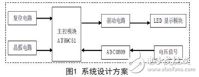
This design selects AT89C51 single-chip microcomputer as the core control device, adopts ADC0809 to realize A/D conversion, and uses 3-digit LED digital tube number to display the acquisition voltage (range 0~5V). The design block diagram is shown in Figure 1.
Third, the hardware part of the design
1. Conversion chip ADC0809
ADC0809 has 8 analog input ports, 8 analog switches are gated to 8 analog channels, and the converted 8 digits are latched into the tristate output latch. When the output allows, 8 can be selected. The data lines D7~D0 are read out and can be directly connected to the MCU interface. The pinout and specific functions of ADC0809 can be found in the ADC0809 documentation, which will not be described in detail here.
2. ADC0809 and microcontroller hardware connection
The interface circuit between the MCU and ADC0809 is shown in Figure 2.
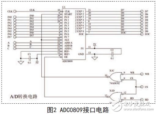
The 74HC02 can realize 4-way 2-input or non-gate functions. When connecting, connect P0.0~P0.7 of the MCU in the host module to the data output terminal D0~D7 of ADC0809, which is used to receive the data of ADC0809 conversion output; P2.5, P3.6, P3.7 of the MCU Connect to the CS, WR, and RD terminals of ADC0809 as the control contact line for A/D sampling; connect A, B, and C of ADC0809 to D0, D1, and D2 of ADC0809, and select the sampling channel of ADC through the control of P0. .
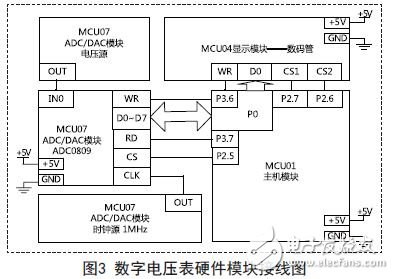
3. Digital voltmeter hardware module wiring
The hardware module wiring required to achieve this task with the YL-236 training device is shown in Figure 3. The circuit consists of a host module (MCU01), a display module (MCU04), and an ADC/DAC module (MCU07). Connect the clock source 1MHZ to the CLK port of the ADC circuit, and provide an input voltage of 0~5V from the analog voltage source.
Commercial grade Led Shoebox Fixture lighting for parking lots and flood light applications!With our collection of Led Shoebox Light Fixture, find the perfect way to illuminate parking lots of any size.Shoebox Light Fixture helps illuminate parking lots and more with LED Area Light commercial light fixtures.
Led Shoebox Fixture
Led Shoebox Light Fixture, Led Shoebox Fixture,Shoebox Fixture,Shoebox Light Fixture
Shenzhen Bbier Lighting Co., Ltd , https://www.chinabbier.com