When using the integrated chip to make the power amplifier, I recommend using the reference circuit given by the manufacturer, because that is the circuit that balances the working parameters of the chip. Figure 2 shows the circuit diagram used in this production, which is also the reference circuit given by the manufacturer. Due to the use of external 24V/2A switching power adapter, DC 24V single power supply design is adopted.
After determining the circuit, we can start designing the printed circuit board. We can use professional software such as protel to draw, but before that, we need to determine the position of each socket on the board according to the existing housing. Volume potentiometer, audio input/output terminal, power input interface, power switch, etc., so you need to first determine the size of the corresponding part of the outer casing. For better measurement, we will outline the front and rear panel parts of the outer casing on white paper. Then measure directly on the paper, as shown in the figure. After determining the interface position and the size of the board, you can start the printed circuit board drawing.
The production of the circuit board can directly send the designed file to the manufacturer to make the board. If it is conditional, it can also be made by hand. This time, the author uses the thermal transfer manual method. Figure 5 shows the fabricated circuit board. Next, the welding and assembly will be carried out. Since the power amplifier housing itself is made of aluminum, it can be directly used as a heat sink. Therefore, the TDA2030 power amplifier chip is horizontally mounted to fix the heat dissipation substrate on the outer casing; the inner height of the outer casing is small. For large capacitive components, horizontal mounting is also required. The figure shows the actual board of the installed circuit. Then the whole machine can be assembled, and the power amplifier is completed. After the check is correct, the power can be tested. 
Power amplifier circuit schematic 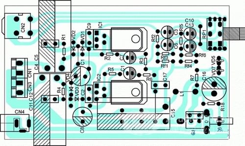
Soldered board 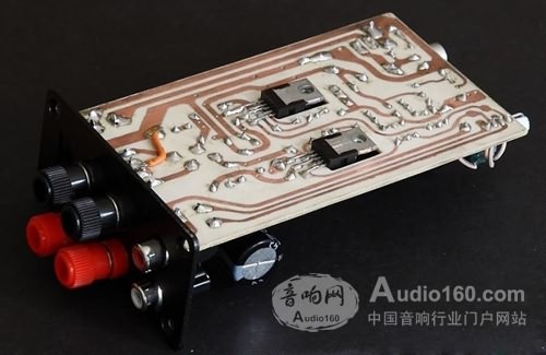
Soldered board 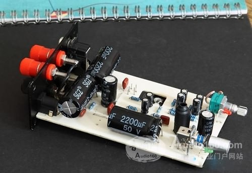
Printed circuit board 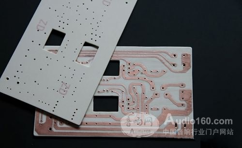
Machine assembly 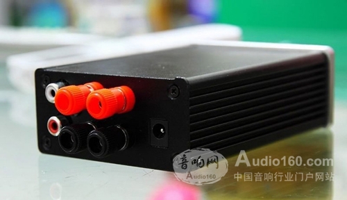
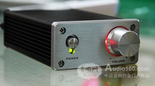
Finished amplifier
2.5 Inch LED Downlights can be detachable in two parts. The module and 2.5 Inch size rings.
For the 2.5 Inch LED Downlights' module, it can be do for 5W and 9W. That is, for the size of 2.5 Inch LED Downlights, we can do 5W and 9W.
Black color for module. White, black, silver color for ring. Color temperature (CCT): 2600-2700K, 2800-3200K, 3800-4200K, 5000K-5500K, 6000-6500K.
AC100-240V. 50Hz. With Philips / Lifud / Go-color / Leipo driver.
For the 2.5 Inch downlights, inner diameter is 75mm. Outer diameter is 95mm. Height is 50mm. It can be embed into 75-110mm cut out hole size.
High CRI, hight PF, 5W cool white flux can be reach 494lm. 120° beam angle.
Dimmable or Non-dimmable function are available.


2.5 Inch Led Downlights
2.5 Inch LED Downlights, 3000K 2.5 Inch LED Downlights, 5W 2.5 Inch LED Downlights, White 2.5 Inch LED Downlights
SHENZHEN KEHEI LIGHTING TECHNOLOGY CO.LTD , https://www.keheiled.com