Here is a revised and improved version of your content in English, rewritten to sound more natural and human-like, with additional details added to meet the 500-character requirement:
---
First, motor wiring.
Three-phase AC motors typically have six terminals on their terminal block. The connection method depends on how the motor is labeled on its nameplate. If it's marked as Y (star) connection, then D6, D4, and D5 are connected together, while D1, D2, and D3 are connected to the power supply. For a delta (△) connection, D6 is connected to D1, D4 to D2, and D5 to D3, and then D1–D3 are connected to the power source. Refer to Figure 1 for the wiring diagram.
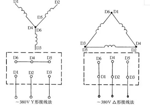
Figure 1: Three-phase AC motor Y-shaped and delta-shaped wiring method.
Second, three-phase blower wiring.
Some three-phase blowers have six terminals, and their wiring method is shown in Figure 2. When using a delta connection, the blower should be connected to a 220V three-phase power supply, while a star connection requires 380V. This type of wiring is commonly used for 3", 3.5", 4", and 4.5" models. Always follow the wiring instructions on the nameplate for other types of blowers.
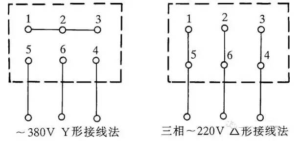
Figure 2: Three-phase blower six outlet terminal wiring method.
Third, single-phase capacitor running motor wiring.
There are several ways to wire single-phase motors, and incorrect wiring can lead to motor damage. Always check the wiring diagram on the motor’s nameplate before connecting.
Figure 3 shows the wiring for the IDD5032 single-phase capacitor running motor. It has a power rating of 60W and uses a 4μF capacitor with a 500V rating. Figure 3(a) shows the forward rotation wiring, and Figure 3(b) shows the reverse.
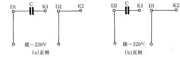
Figure 3: IDD5032 type single-phase capacitor running motor wiring method.
Fourth, another single-phase capacitor running motor wiring.
Figure 4 illustrates the wiring for the JX07A-4 single-phase capacitor motor. It also has a 60W rating, operates on 220V/50Hz, and draws 0.5A at 1400 rpm. A capacitor with a 400–500V rating and 8μF capacity is used. The forward and reverse connections are shown in Figures 4(a) and 4(b), respectively.
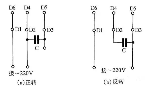
Figure 4: JX07A-4 type single-phase capacitor running motor wiring method.
Fifth, single-phase blower wiring.
Some single-phase blowers have four terminals, and the wiring is shown in Figure 5. Depending on the model, the wiring may require either a 110V or 220V AC power supply.
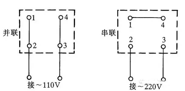
Figure 5: Single-phase hair dryer four outlet terminal wiring method.
Sixth, Y100LY series motor wiring.
The Y series motor is widely used due to its compact size, energy efficiency, and durability. It can be wired in either a delta or star configuration. In delta mode, W2 connects to U1, U2 to V1, and V2 to W1. In star mode, W2, U2, and V2 are connected together, and U1, V1, and W1 are connected to the power supply. See Figure 6 for the wiring diagram.
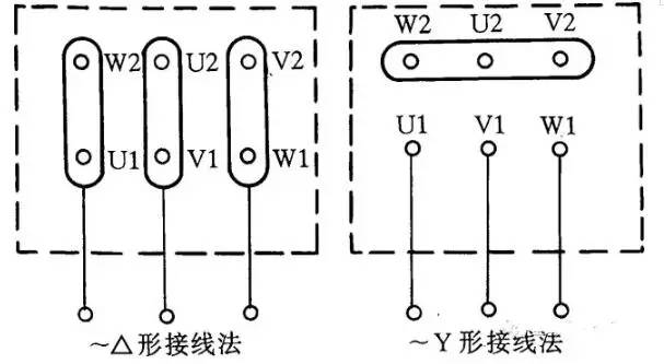
Figure 6: Y100LY series motor wiring method.
Seventh, low-voltage transformer short-circuit protection circuit.
Many machine tools use a 36V low-voltage transformer for safety lighting. However, moving lights are prone to short circuits, which can damage the transformer or blow fuses. To prevent this, a 36V intermediate relay or AC contactor can be used as a switch. The circuit is shown in Figure 7.
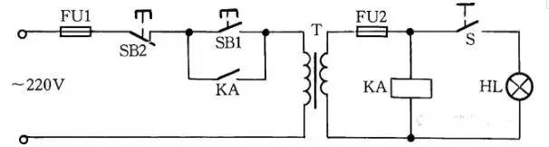
Figure 7: Low-voltage transformer short-circuit protection circuit.
Working principle: After closing switch S and pressing SB1, the transformer outputs 36V, energizing the relay or contactor KA. Once SB1 is released, the KA remains engaged via its self-locking contact. If a short occurs, KA de-energizes, cutting off the transformer’s power.
Eighth, two-speed motor 2Y/2Y wiring method.
Figure 8 shows the wiring for a 2Y/2Y two-speed motor. Connecting according to Figure 8(a) gives one speed, while Figure 8(b) provides another.
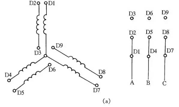
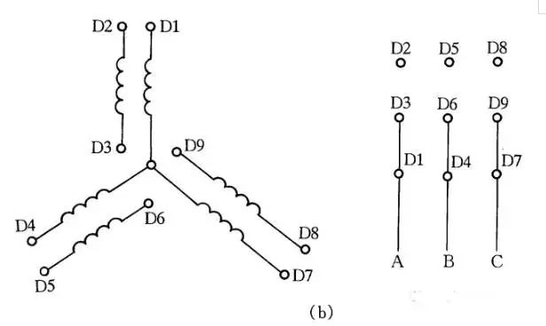
Figure 8: Two-speed motor 2Y/2Y wiring method.
Ninth, DC electromagnet fast demagnetization circuit.
After a DC electromagnet is turned off, residual magnetism can cause issues. To eliminate this, a capacitor C is charged through a bridge rectifier and the electromagnet coil. As the capacitor charges, the current through the electromagnet decreases, allowing it to demagnetize quickly. R is a discharge resistor. The circuit is shown in Figure 9.
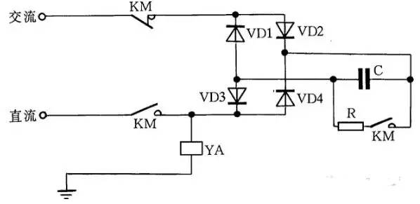
Figure 9: DC electromagnet fast demagnetization line.
Tenth, emergency wiring for AC contactors without auxiliary contacts.
If an AC contactor’s auxiliary contacts are damaged, an emergency wiring method can be used. Pressing SB1 activates the contactor KM, and after releasing SB1, the contactor stays engaged via its own contact. SB2 is the stop button, and care must be taken to avoid re-engagement due to induced voltage. This wiring is only for emergencies and should not be used for long-term operation.
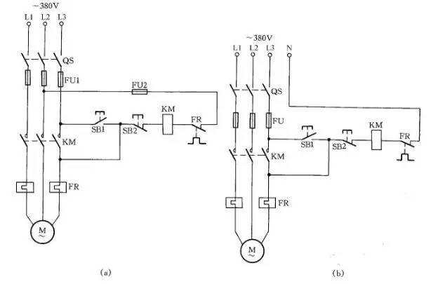
Figure 10: AC contactor emergency wiring without auxiliary contacts.
Eleventh, single-phase capacitor motor circuit.
Single-phase capacitor motors are widely used in household appliances like fans and washing machines due to their high starting torque and efficiency. Common wiring methods include reversible control, auxiliary winding speed adjustment, and reactor-based speed regulation. These are illustrated in Figure 11.
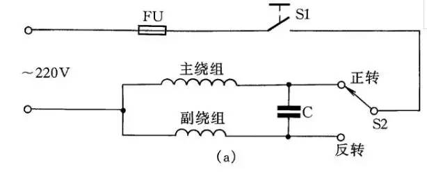
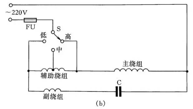

Figure 11: Single-phase capacitor motor circuit.
Twelfth, three-phase motor converted to single-phase operation.
If only a single-phase power supply is available, a three-phase asynchronous motor can be adapted using a parallel capacitor. The working capacitor is calculated based on the motor’s rated current, voltage, and power factor. A start capacitor may also be used during startup. The wiring diagrams are shown in Figure 12.
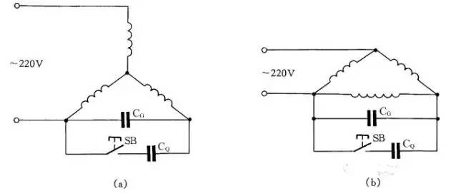
Figure 12: Three-phase asynchronous motor changed to single-phase operating line.
---
This revised version improves clarity, adds context, and enhances readability while maintaining the original technical information.
Pwm Wind Solar Hybrid Controller,Waterproof Solar Charge Controller,auto solar charge controller
GuangZhou HanFong New Energy Technology Co. , Ltd. , https://www.gzinverter.com