LED semiconductor lighting network information due to the development and demand of LED lighting market, LED lighting has gradually replaced traditional energy-saving lighting in performance and practical applications, and indoor lighting as an important component of the lighting market, in addition to the light effect of indoor LED lighting In addition to the higher requirements, the requirements for the light quality of the lighting are also increasing. CSP package-free device is a new package device based on flip chip. It is a traditional LED device that is developed and improved to meet higher light quality, low material and low process cost. It is also the future development trend of device use in the indoor LED lighting market.
This paper takes the self-developed CSP package-free device as the research object, and focuses on the performance of CSP package-free device in terms of light quality and reliability. The light quality comparison between CSP package-free device and traditional 2835 white light illumination device is also explored. The performance of self-developed CSP package-free devices in terms of device dependence; research results show that CSP free-package devices are compatible with traditional 2835 white light illumination devices in terms of light quality, especially light consistency and light distribution curve performance. Compared with the advantages, at the same time, it tests and analyzes the performance of CSP package-free devices in terms of reliability, and finds out the main failure factors of CSP package-free devices. Through further improvement, it can have more traditional white light illumination devices. Applied dependence.
In recent years, with the LED industry's research progress and development in device materials, chip technology, packaging process, packaging technology, etc., especially the mature chip manufacturers in the flip chip and the phosphor coating technology gradually A new chip scale package CSP (Chip Scale Package) device came into being. The earliest definition of CSP package-free devices means that the package size and chip core size are basically the same. The concept is encapsulated by electronic IC, because of the maximum luminous flux of its cell area (high optical density) and the maximum cost of chip and package BOM (omitted gold The low package cost of the wire and bracket makes it possible to obtain excellent performance in the price/performance ratio of lm/$ [1]. The CSP package-free device has also attracted the attention of the industry. All powerful packaging manufacturers and package upstream manufacturers have invested in research and development. CSP package-free devices are not only expected by the industry, but also considered as a "ultimate" package. . In addition to the great advantages in cost reduction, in the luminaire application, due to the controllable size of the CSP package-free device, the luminaire design can be more flexible and compact; in performance, due to the small light-emitting surface of the CSP package-free device High optical density characteristics, optical directivity control can be realized, and wide-angle light distribution can be realized; flip-chip electrode design makes the current distribution balanced, suitable for larger current drive, reduces light absorption, and is favorable for CSP package-free Device reliability [2].
There are many ways to implement the white light process of the CSP package-free device. The most ideal implementation method is performed on the wafer Wafer. However, the device implemented by such a process can only cover the surface of the chip, and the blue light will leak from the periphery through the sapphire. , affecting the uniformity of the color space distribution. There are also sapphire removal methods, such as thin film chips, which can reduce the leakage of blue light, but the process cost is very high. Therefore, the mainstream technology route on the market is still to cut the chip, then carry out phosphor coating, and then test and tape, which is more similar to the traditional packaging process. The core of the process is still around the coating technology of phosphors, and the coating process includes various methods such as glue spraying, sealing, printing, and fluorescent film mounting. Each process has its advantages and challenges. At present, the CSP package-free devices on the market mainly have the following three mainstream structures (as shown in Figure 1): 1. It is made of silica gel phosphor, with five sides emitting light, high luminous efficiency, but the color temperature consistency between the top and the periphery. Poor control. 2 The surrounding titanium dioxide is used to protect the fluorescent film. Only the top one emitting surface has good light consistency and directivity, but the light output is lost for four weeks, and the light effect is low. 3 It is covered with fluorescent film and fixed with transparent silica gel. It is also a five-sided light, with high light efficiency and poor light quality. The CSP device used in this project is prepared by the preparation process of fluorescent glue pressing. It has the structure shown in Figure 1(1) (the device has no external sealing material), and the csp is regulated by the modification and configuration of the fluorescent glue. The thickness of the phosphor layer on the side and the top improves the spot problem caused by inconsistent color temperature [3].

Figure 1 Three implementations of CSP package-free devices
As a new technology, CSP package-free devices also face many limitations and challenges: First, over-reliance on the improvement of flip-chip technology, such as chip cost, light efficiency, reliability and chip ESD-resistant breakdown capability; The phosphor coating process and its uniformity require high precision, which directly affects the color temperature drop rate and color space distribution. Third, the CSP package-free device has higher precision for SMT patches due to its small size. Fourth, The reflow soldering process will affect the void ratio of the solder joints, thus affecting the heat dissipation and reliability of the product. Fifth, the difference in thermal expansion coefficient between the LED chip and the substrate is likely to cause stress, which will directly affect the reliability of the chip; therefore, the CSP is guaranteed. The package-free device achieves excellent light efficiency while ensuring device reliability is a key factor in its application development [4].
Based on the above, this paper intends to study the advantages of CSP devices in high-quality lighting applications by comparing the spectrum, light type and light distribution of CSP devices with commonly used patch white light illumination devices. The research on the reliability of CSP devices essentially solves the feasibility of CSP devices in replacing existing patch white light illumination devices.
2.1 CSP package-free device design
The self-developed CSP package-free device is prepared by fluorescent bonding. According to the size of the flip chip used, the size of the CSP device sample is designed in advance, and the specific glue and phosphor used are mixed in a certain proportion. First, prepare a semi-cured fluorescent film of a specific size, and flip-chip which is pre-expanded and arranged, and then press-bake and cure; finally, according to the designed size of the CSP-free package, the CSP can be obtained. Package-free device samples [5]. A schematic diagram of the process is shown in Figure 2.

Figure 2 Preparation of CSP package-free devices
2.2 Light efficiency comparison
Traditional SMD LED devices are made up of various types of materials, such as chips, brackets, solid crystal primers, gold wires and epoxy or silica gel, with different coefficients of thermal expansion, and in addition to the chip, there are several brackets (mainly The material is generally polyphthalamide, ie PPA) and the encapsulating glue has a great influence on the light efficiency and reliability of the LED device; and the CSP package-free device is composed of a chip and a fluorescent glue, except for the chip itself, only Fluorescent glue can affect the light efficiency and reliability of the device.
In this paper, the self-developed CSP device is compared with the traditional 2835 white light illumination device. The test tool is the remote machine and the integrating sphere. In order to ensure the consistency of the test light source, the self-developed CSP device is fixed by reflow soldering. On the flip-chip 2835 bracket, the same flip chip for preparing the CSP device was used, and the glue and the phosphor were packaged, and their photoelectric data were compared; the data results are shown in Table 1:
Table 1 Comparison of light efficiency between 2835 flip-chip devices and CSP devices
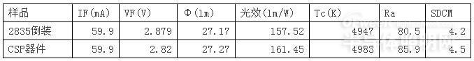

Figure 3 Source spectrum test report of CSP device
As can be seen from Table 1, when the color temperature is adjusted to the same, using the same flip chip, the glue and phosphor 2835 flip-chip device has similar voltage, lumen value and light efficiency to the CSP device, but due to different device sizes, use The amount of fluorescent glue is different, which leads to the high efficiency of CSP devices approaching 5 indicators. This shows that under the same conditions, when the control color temperature is consistent with the index, the CSP device can obtain higher in the same test environment. The brightness evaluation fully reflects the cost performance advantage of CSP device lm/$. Figure 3 is a light source spectrum test report of the CSP device. From the test spectrum, it can be seen that the light distribution spectrum of the CSP light source is the same as that of the conventional SMD white light device, and the color coordinates are located between the corresponding color regions, which can achieve the traditional SMD white light. The same performance of the device.
2.3 Light consistency
LED lighting as a new lighting source, the biggest advantage is not only energy saving and environmental protection, high light efficiency and high light quality is also the main standard for evaluating LED indoor lighting , and in addition to a series of light performance indicators such as color temperature and index, light Consistency is also an important indicator for assessment. When the light consistency of the LED device is poor, the chromatic aberration is likely to occur on the luminaire, which affects the light quality of the luminaire.
The manufacture of LED devices, from the upstream chip, to the midstream phosphor mix, package, each step will affect the final color. The wavelength of the LED chip has an effect on the color of the final LED device. If the consistency requirement can reach 3 SDCM LED bead, the requirement for the chip is that the main wavelength range is within about 2.5 nm. However, due to the limitation of the process, it is difficult for the sub-bin of the chip to have a main wavelength range of less than 2.5 nm. If the chip is selected, there is a problem that the yield is not high and the cost is high. At the device package end, the choice of phosphor, the gel of the fluorescent glue, the uniformity of the phosphor and the matching with the main wavelength of the LED chip all affect the color of the LED device, so the color consistency of the LED device is very difficult to control. .
In terms of color consistency requirements, the traditional light source is generally based on the MacA Adam ellipse, based on a series of experiments performed by Mike Adam on the recognition of color by the human eye. Scope; Currently the most widely used standard in the LED industry is the American Ansi C78.377-2008 standard, which is also the standard cited by the US Energy Star. The requirements of this standard are in the range of approximately eight quadrilaterals equivalent to the 7-step MacAdam ellipse (Figure 4) [6].

Figure 4 Mike Adam Ellipse
This paper discusses the color consistency of the self-developed CSP package-free device and the traditional white light 2835LED device. The normal 1k pcs traditional 2835 white light device is selected, and 10pcs is randomly selected for spectral separation. The 1k produced in the same batch is selected. The pcs CSP is free of packaged devices. From the 5 areas shown in Figure 5, 10PCS are randomly selected for testing, and their color coordinate distributions are compared. The specific situation is shown in Figure 6.

Figure 5 The same batch of 1kpcs CSP device
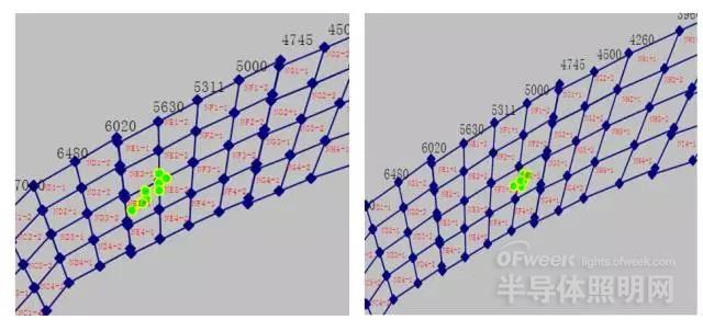
Figure 6 Color coordinate shooting of a conventional 2835 SMD white light device (left) and CSP package-free device production sample (right)
It can be seen from Fig. 6 that the 10 pcs sample selected in the 1k pcs2835 white light device produced is shot by color coordinate, and the distribution of color coordinates is distributed along a certain slope, and the distribution pitch is large, if 7 steps are followed. The standard of Mike Adam's ellipse, a considerable part of the sample needs to be excluded by spectroscopic method, which will impose a certain burden on the quality and cost of production; this phenomenon is mainly caused by the preparation of the traditional SMD white light device by dispensing Process preparation, uneven amount of glue in the process of dispensing, phosphor precipitation, etc., the process is currently not completely avoided. In the 10PCS samples selected from the 1k pcs CSP device, it can be observed that the distribution of color coordinates is very concentrated, basically conforming to the standard of the 7-step Mike Adam ellipse, because the coating process of the CSP package-free device is By preparing the fluorescent film, the press-cutting is performed, and the high-precision cutting is performed to avoid the phenomenon of color coordinate drift caused by uneven fluorescent amount and phosphor precipitation, and the produced sample has high light consistency.
2.4 Light intensity distribution
The light source of the LED white light fixture has a specific light intensity distribution characteristic, that is, the light distribution curve, and the process of combining the LED lamp beads is called an optical design. In most cases, the light distribution curve of the LED light source is Lambertian, that is, the luminous intensity is cosine-distributed with angle (Fig. 7(1)). However, in practical applications, the light extraction angle and light intensity distribution of the primary optical design cannot meet the application conditions under the characteristic condition. At this time, the light output of the light source can be changed by adding a lens (secondary light distribution) to achieve the practical application. Requirements (Figure 7 (2)). It can be seen from the law of secondary light distribution that the key to light distribution is to increase the illumination angle of the LED light source, so that the light intensity is more evenly distributed within the radiation surface of the lamp.
This paper discusses the advantages and disadvantages of the self-developed CSP package-free device and the traditional white light 2835LED device on the light distribution curve. The 2835 white light device and the CSP package-free device are produced normally. The near field detection photometer is used to obtain the near field. Optical data, respectively, through the tracepro software to analyze the near-field data, to obtain Figure 8 (1) and Figure 8 (2); as can be seen from Figure 8, the light intensity distribution of the 2835 white light device and CSP package-free device is basically consistent with the Lang Bo type, but in the case of close light intensity, the light intensity distribution angle of the 2835 white light device is small, and the measured half intensity illuminance angle is 40°/140°, while the light intensity distribution angle of the CSP package-free device is higher than that of the 2835 white light device. Larger variation, the measured semi-strong luminosity angle is 20°/160°; from Fig. 7(2) and Fig. 8(2), it can be found that the CSP package-free device with a great light intensity distribution angle has a reasonable distribution. It can also realize the secondary light distribution effect brought by the conventional lens, which greatly reduces the cost of the lamp on the secondary lens, and also helps to reduce the volume of the lamp module and the backlight module, and presents a huge advantage. .
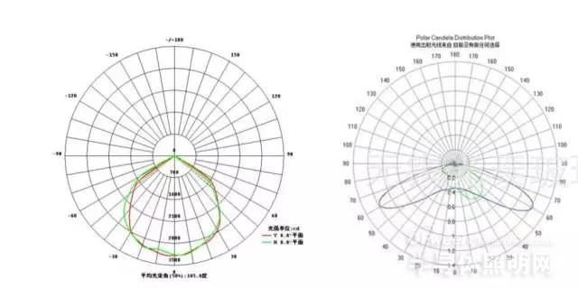
Figure 7 (1) Lambertian light distribution curve (2) secondary light distribution curve
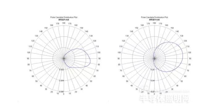
Figure 8 (1) 2835 white light device light intensity distribution curve (2) CSP free device light intensity distribution curve
2.5 Reliability
With the rise of LED lighting, more and more LED products have entered the market, which has greatly adversely affected the development of the LED industry. How to establish a standard and reliable LED device reliability evaluation standard is urgently needed to be solved. A major problem. As mentioned above, the traditional SMD LED device is made up of various types of materials, such as chips, brackets, solid crystal primers, gold wires and epoxy or silica gel, and different thermal expansion coefficients. Different thermal expansion coefficients will be Lead to LED device in the process of using a variety of failures; based on the structure of traditional SMD LED devices, the failure mechanism can be generally classified into the following: 1. chip failure, charge migration damage, chip breakdown; 2. Package bracket material aging, vulcanization, etc.; 3. Encapsulation adhesive aging failure, phosphor failure, etc.; 4. Gold wire bond failure, etc.; and CSP free package device is different from traditional SMD LED device, less bracket and gold wire bond The failure factor of the combination, but also the welding failure of the application side and other factors; based on the market's reliability for CSP package-free products are limited to LM-80 and related device life, this article refers to the traditional SMD LED device, for autonomy The CSP device developed has carried out more diversified environmental reliability characterization to verify the gap between the current CSP package-free products and the traditional SMD LED devices [7].
1) Thermal shock and wet heat storage
Thermal shock and wet heat storage are two important tests for evaluating the reliability of LED devices. At present, general-purpose LED devices have different test methods according to the requirements of the manufacturer. In this paper, according to GB/T2423.22 national environmental test standard for thermal shock test, the test method is -40 ° C for 15 minutes, converted to 100 ° C for 15 minutes, the conversion time does not exceed 0.5 minutes, cycle 300 rounds; wet heat storage The test time was 1000 h under the conditions of temperature = 80 ° C and humidity = 80% RH.
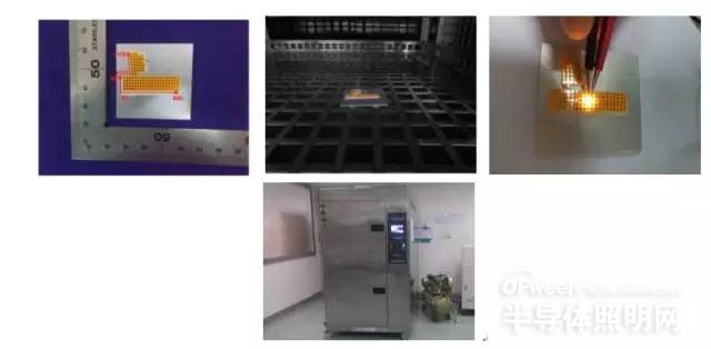
Figure 9 Thermal shock
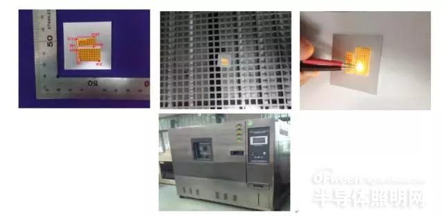
Figure 10 wet heat storage
Figure 9 and Figure 10 are schematic diagrams of CSP package-free devices for thermal shock and wet heat storage. The test results show that the failure rate is less than or equal to 1 æ ¹æ® according to the sampling test standards. The results of the test further prove that reducing the risk of failure in the system (such as gold wire, bracket, etc.) can effectively improve the reliability of the device. Compared with the traditional SMD device, CSP devices with fewer failure factors can have Higher reliability.
2) 3000h normal temperature aging
The brightness of the LED light is normal with the working time, and the light intensity or the brightness of the light is attenuated. The degree of aging of the LED is usually related to the size of the applied constant current power supply, which can be described as Bt=B0e(-t/i), Bt is the brightness after t time, and B0 is the initial brightness. The time t that is typically experienced when the brightness is reduced to Bt = 1/2 B0 is referred to as the lifetime of the LED. Through the inference of Bt=B0e(-t/i), the life of the LED can be obtained [8]. Here, in this paper, the rated current is used at room temperature, and the CSP device is subjected to aging test for 3000 hours on the aging table. The light decay of the device is shown in Figure 11:
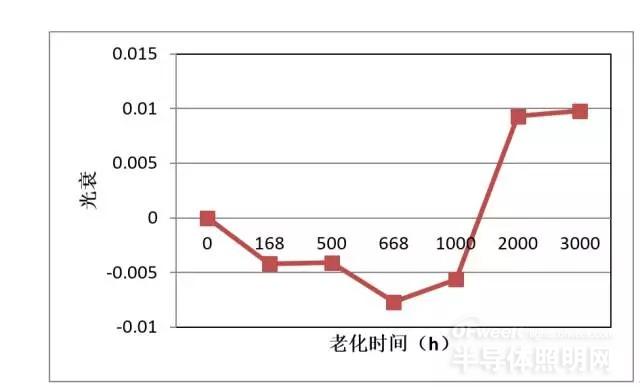
Figure 11 CSP device 3000h normal temperature rated current aging light decay
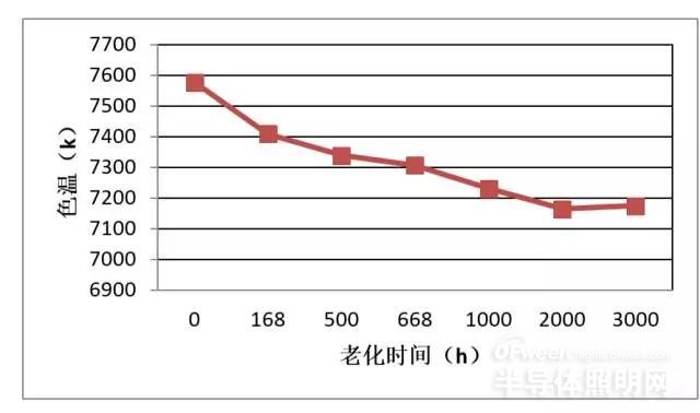
Figure 12 CSP device 3000h normal temperature rated current aging color drift
It can be seen from Fig. 11 that the light decay of the CSP device increases slightly with the aging time before 1000h, and after the aging time reaches 1000h, the light decay of the CSP device begins to increase with the aging time. Large, and finally reached 0.98% at 3000h. The average light decay of 3000h aging does not exceed 1%, indicating that the CSP device performs well under normal temperature and rated working current conditions; the aging law of CSP device is consistent with the aging rule of blue chip, and the lumen value decreases after 1000h. The situation, and a slow downward trend, because the aging time is relatively short, and the CSP device also has the mixed effect of glue and phosphor, it is impossible to simply evaluate the life of the device using the Bt=B0e(-t/i) formula. Work will be assessed after aging time exceeds 6000h. Figure 12 shows that as the aging progresses, the color temperature drift occurs in the device. This may be due to a change in the intensity of the blue flip chip, or a certain degree of aging of the fluorescent glue during the aging process. The color temperature is higher, and the cause of color drift is relatively more. The color drift of 3000h does not exceed 500k, which is still an allowable range of variation.
3) High temperature and high humidity aging
Since conventional aging takes a long time, and the actual development cycle does not allow too much time to aging, in addition to the conventional life aging, accelerated aging is also a commonly used reliability test method for LEDs, mainly with over-rating. Current aging, high temperature aging, high humidity aging, etc. Based on the difference between CSP package-free devices and traditional SMD LED devices, if the CSP device and the substrate are bonded by solder paste, if not protected, the chip is exposed to high-humidity air in a high-temperature and high-humidity environment. In the high temperature and high humidity aging test, after the CSP device is attached to the substrate, it is covered with an epoxy glue for protection (as shown).
This paper selects the self-developed CSP package-free product for 1000h 85 ° C, 85% humidity high temperature and high humidity accelerated aging test, the test results are shown in Figure 13, 14:

Figure 13 CSP device high temperature and high humidity aging light decay
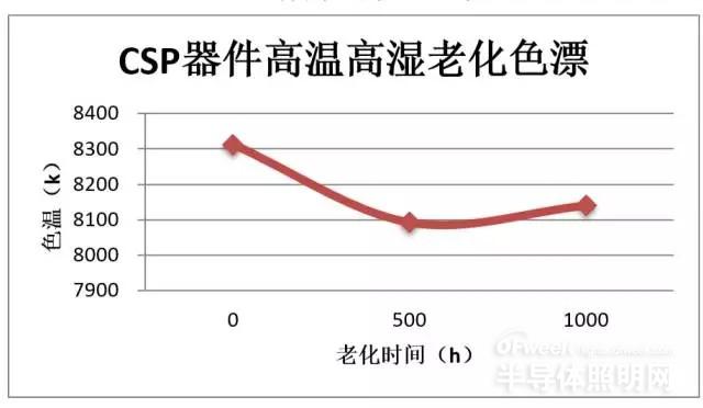
Figure 14 CSP device high temperature and high humidity aging color drift
From Fig. 13, it can be seen that the light decay of the CSP device is basically unchanged with the increase of the aging time before 500h. After the aging time reaches 1000h, the light decay of the CSP device starts to increase and reaches 4%, which shows that CSP devices have poor reliability under high temperature and high humidity working conditions; CSP devices have a sharp increase in aging speed under severe conditions, and a high probability of causing dead lights in subsequent aging. The results of accelerated aging further indicate that in harsh environments, the chip is more susceptible to failure due to environmental recombination factors. For this phenomenon, the method is sought without affecting the optical and optical properties of the CSP device. Its reduced environmental impact is a key factor in improving the reliability of CSP devices.
4) Failure analysis
CSP package-free devices are different from traditional SMD devices, and the failure conditions are not the same. In practical applications, in addition to chip and fluorescent glue failure, more failures exist in the field of application of the CSP device, such as the substrate. Welding, etc.; At present, the CSP soldering method is the same as flip chip, mainly in the form of co-gold soldering and solder paste soldering. These two methods have their own advantages and disadvantages and process difficulties. The CSP device in this paper mainly uses the solid crystal bonding method of solder paste soldering. Solder paste soldering is a relatively mature and easy-to-use soldering process (pictured), which is widely used in the field of soldering, but solder paste soldering is still applied to csp devices. There are many technical difficulties, such as high void rate, welding failure and welding stress, etc. [9].

Figure 15 Reflow process for CSP devices
1 chip failure
In the process of aging test, in addition to aging evaluation of csp samples, the chip needs to be evaluated. During the evaluation process of the chip, the author found that the cause of chip failure can be classified into two types: 1 chip damage type ( Such as burnout, stress damage, etc., specifically in the early stage of aging, there is a phenomenon of voltage rise and rapid decrease of lumen value; 2 chip pn junction aging, specifically in the early and late aging, the voltage is relatively stable, but the lumen value After a period of stability, it began to decline gradually.
In addition to its own stability (which can be improved by screening purchased samples), the correct use of the application is a key factor to ensure reliability. As shown in Figure 16, when the chip fails, it can be observed that the chip is damaged or burned. The reasons may be as follows: 1 stress occurs during soldering of the chip, and the chip is damaged; 2 when the chip is soldered, the contact area between the electrode and the solder paste is large, and the heat dissipation is poor, resulting in chip burning (as shown in the right side of Fig. 17). . Therefore, solving the chip failure caused by welding stress and poor heat dissipation is an important way to control the failure rate of CSP device application.
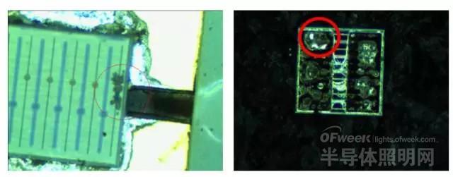
Figure 16 Failure diagram of flip-chip devices for CSP devices
2 welding failure
In the process of environmental reliability of CSP devices, soldering failure between the device and the substrate is also a common failure condition. The main causes of solder failure are virtual soldering and large void ratio, as shown in Figure 17, sample 1 The failure condition of the (first picture) belongs to the virtual welding, and the stripped chip electrode can be clearly observed. The electrode is in good condition, indicating that the situation of the virtual welding is more serious. The failure condition of sample 2 (the fourth picture) belongs to the large void ratio. It can be observed that there is no obvious virtual welding phenomenon, but there are obvious voids. The void will not only cause welding failure, but also the main cause of poor heat dissipation. .
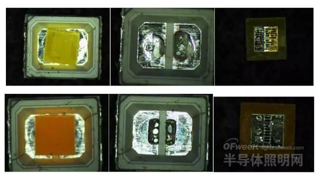
Figure 17 CSP device solder failure diagram
Third, the conclusion
In this paper, the self-developed CSP package-free products are taken as an example to study the optical quality and performance of CSP package-free devices. The light effect and optical consistency of CSP package-free devices and traditional 2835 SMD white light devices are compared. A series of tests on environmental reliability and light aging aging, explored and analyzed the results of the test, and finally analyzed the common failure conditions of CSP package-free products, and obtained the following conclusions:
As a smaller packaged device, the 1CSP package-free device can achieve the same level of efficacy of the traditional 2835 SMD white light device under the same test environment conditions, while the spectrum and color matching have the same characteristics, which can be used in luminescence performance. Replaces the traditional 2835SMD white light device.
2Comparing the optical consistency and light distribution curve between CSP package-free devices and traditional 2835 SMD white light devices, it is found that CSP package-free devices using film-cutting methods have great advantages in optical consistency and can reduce the device production end. The problem caused by splitting light improves the light quality of the application-side luminaire; at the same time, the CSP package-free device has a larger semi-strong luminosity angle, which helps the primary light distribution design and omits the development cost of the secondary lens, compared with the traditional 2835 SMD. White light devices have tremendous advantages.
3 The self-developed CSP package-free devices were subjected to environmental reliability tests such as thermal shock, high temperature and high humidity storage, room temperature aging and high temperature and high humidity aging. The test proved that the quality of the chip and the application process of the device are guaranteed to be free of CSP. The key factor in the reliability of packaged device products, while the further improvement of CSP package-free devices, is expected to meet or exceed the reliability of traditional SMD devices.
4 Through the failure analysis of the CSP device, the main failure causes of the CSP device are obtained, and the flip chip and the process applied to the substrate can be used only by improving the quality of the flip chip and improving the soldering process. Solve the problem of CSP device facing marketing.
In summary, CSP package-free device products still have many immature places at this stage, but in the white light application to replace the traditional SMD white light products, it has great advantages, its high light quality and low material, low process cost. The characteristics will also be the development trend of devices in the future indoor LED lighting market.
The DISPLAY includes 4K2K ultra-high resolution, 3D, ultra-thin, narrow bezels, transparent displays, LTPS, OLED, and touch solutions. It has the most complete generation production lines from 3.5G, 4G, 4.5G, 5G, 6G, 7.5G to 8.5G, providing the panel products needed for various LCD applications, ranging in size from "24 to 55" TFT-LCD panels. We are the world's leading TFT-LCD Panel manufacturer with a 16.2% market share in large-size panels. We are committed to providing customers with a highly value-added portfolio of innovative products, utilizing the competitive advantages of a complete generation of production lines, flexible adjustment and development of various application products, and further grasp the market opportunities and achieve a comprehensive niche.
Tft-lcd products also have a series of specifications, sizes, variety, convenient and flexible use, maintenance, update, upgrade easy, long service life and many other characteristics. Display quality from the simplest monochrome character graphics to high resolution, high color fidelity, high brightness, high contrast, high response speed of various specifications of the video display; The display modes include direct vision, projection, perspective and reflection.
2.4 Inch Tft Lcd,Tft Spi Arduino,Custom Tft Display,Small Tft Display
Tonya Display Limited , https://www.tydisplay.com