Touch technology has been widely used in consumer electronics such as smartphones and tablets. This article explains the principle and classification of touch screen technology, hoping to help readers.
Touch screen technologyTouch screen technology is a new type of human-computer interaction input. Compared with traditional keyboard and mouse input methods, touch screen input is more intuitive. With the recognition software, the touch screen can also realize handwriting input.
Classification of touch screen technologyAccording to different screen surface positioning principles, the touch screen technology can be divided into two types: acoustic pulse recognition (APR) technology, surface acoustic wave (SAW) technology capacitive touch screen technology and resistive touch screen technology infrared/optical technology.
Acoustic Pulse Recognition (APR) technology APR consists of a glass display coating or other hard substrate with four piezoelectric sensors mounted on the back. The sensor is mounted on two opposite corners of the visible area and connected to the control card via a bent cable. When the user touches the screen, the drag between the finger or the stylus and the glass collides or rubs, and sound waves are generated. The wave radiation leaves the contact point and is transmitted to the sensor to generate an electrical signal in proportion to the sound wave. These signals are amplified in the control card and then converted to a digital data stream. The data is compared with a list of previously stored sounds to determine the location of the touch. APR is designed to eliminate environmental influences and external sounds because these factors do not match the stored sound list.
Surface Acoustic Wave (SAW) Technology The SAW touch screen is a glass coating with a transmitting and receiving piezoelectric sensor for the X and Y axes. The controller sends an electrical signal to the transmitting sensor and converts the signal into ultrasonic waves within the surface of the glass. These waves cover the entire touch screen through the array of reflectors. The opposite reflector collects and controls these waves to the receiving sensor, converting them into electrical signals. Repeat this process for each axis. A portion of the propagating wave is absorbed by the user when touched. The received signals corresponding to the X and Y coordinates are compared to the stored digital distribution map to identify the changes and calculate the coordinates.
Touch screen principleResistive touch screen technology Resistive screen is a touch screen technology that utilizes the change of the pressure of the touch screen surface to produce a precise change in the resistance caused by the deformation of the screen. The performance of the resistive screen has the following characteristics: 1 They are all working environments that are completely isolated from the outside world. They are not afraid of dust, water vapor and oil. They can be touched by any object. They can be used for writing and drawing. This is their big advantage. The accuracy of the resistive touch screen depends only on the accuracy of the A/D conversion, so it can easily reach 4096*4096. According to the implementation principle, the resistive touch screen is divided into four lines and five lines. The surface acoustic wave (SAW) type SAW touch screen is a glass coating with a piezoelectric sensor for transmitting and receiving for the X and Y axes. The controller sends an electrical signal to the transmitting sensor and converts the signal into ultrasonic waves within the surface of the glass. These waves cover the entire touch screen through the array of reflectors. The opposite reflector collects and controls these waves to the receiving sensor, converting them into electrical signals. Repeat this process for each axis. A portion of the propagating wave is absorbed by the user when touched. The received signals corresponding to the X and Y coordinates are compared to the stored digital distribution map to identify the changes and calculate the coordinates. Touch screen principle
The touch screen is attached to the surface of the display for use with the display. The analog electrical signal is generated by touch, and the coordinates of the touched point are calculated by the microprocessor after being converted into a digital signal, thereby obtaining the operator's intention and executing. The touch screen can be divided into five categories according to its technical principle: vector pressure sensing type, resistive type, capacitive type, infrared type and surface acoustic wave type, wherein the resistive touch screen is used more in practical applications. The resistive touch screen consists of 4 layers of transparent thin film, the bottom layer is the base layer made of glass or plexiglass, and the top is a layer of plastic layer which is hardened and smoothed to prevent scratching, and is attached to the inner surface of the upper and lower layers. It is a metal conductive layer (OTI, indium oxide), which is insulated by fine transparent isolation points. When the finger touches the screen, the two conductive layers are in contact at the touch point.
The two metal conductive layers of the touch screen are used to measure the coordinates of the X-axis and Y-axis directions, respectively. The conductive layer used for the X coordinate measurement draws two electrodes from the left and right ends, denoted as X+ and X-. The conductive layer used for the Y coordinate measurement leads two electrodes from the upper and lower ends, denoted as Y+ and Y-. This is the lead structure of the four-wire resistive touch screen. When a voltage is applied across a pair of electrodes, a uniform continuous voltage distribution is formed across the conductive layer. If a certain voltage is applied to the pair of electrodes in the X direction, and no voltage is applied to the pair of electrodes in the Y direction, the voltage at the contact can be reflected on the Y+ (or Y-) electrode in the X parallel voltage field. By measuring the voltage of the Y+ electrode to ground, the X coordinate value of the contact can be known. Similarly, when a voltage is applied to the Y electrode pair and no voltage is applied to the X electrode pair, the Y coordinate of the contact can be known by measuring the voltage of the X+ electrode. The measurement principle is shown in Figure 1.
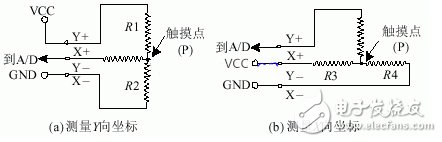
Figure 1 Four-wire touch screen measurement principle
The five-wire touch screen is different from the four-wire type. The main difference is that the five-wire touch screen draws out the four ends of one of the conductive layers as four electrodes, and the other conductive layer only outputs the voltages in the X and Y directions as the measured conductors. The measurement is alternated in the X and Y directions. Apply voltage.
How the touch screen controller worksThere are many kinds of touch screen controllers. The main functions are to apply voltage to the two directions of the touch screen under the control of the microprocessor, and transmit the corresponding voltage signals to the A/D converter. The digital signal is read into the microprocessor by the synchronous clock provided by the port. The basic structure of the controller ADS7846 is shown in Figure 2.

Figure 2 ADS7846 basic structure
Figure 1 shows the measurement results at touch point P as follows: 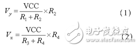
The resolution of the A/D converter can be set to 8 or 12 bits by the setting of the register inside the ADS7846. In this system, the resolution of the A/D converter is 12 bits. Then the binary output code of point P is: 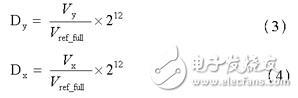
Where: is the reference voltage applied to the ADS7846 internal A/D converter.
The operation of the touch screen controller is controlled by the serial data input port DIN input control command. The basic format of the control command is as follows:
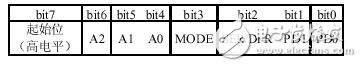
Bit 7 indicates the start of the send command and is active high. A2: A0 is used to select the data input channel, 101 is selected for X coordinate measurement, and 001 is selected for Y coordinate measurement. MODE defines the resolution of the internal analog-to-digital converter as 8 bits (MODE = 1) or 12 bits (MODE = 0). SER/DFR is a single-ended/double-ended reference voltage select bit. PD1: PD0 is selected according to the needs of the power saving mode. The settings of these command control bits will be applied in the program code section.
Weighing display is an instrument that displays the mass and weighing status of the weighed object in electronic instrument. Weighing display is originally analog indicator type, which consists of error amplifier, reversible motor, Balance Bridge, excitation power supply, Dial, Pointer and other parts, and works according to the principle of automatic balance electronic potentiometer. It has slow weighing speed, single function and low accuracy, and has been basically eliminated now. The current weighing display is digital display.3 Inch Weight Indicator,5 Inch Weight Indicator,Large Size Weighing Display,Large Screen,External Large Screen Of The Instrument
Large screen, large size weighing display, external large screen of the instrument, 5 inch weight indicator, 3 inch weight indicator.
Ningbo Santwell Imp & Exp Co.,Ltd , https://www.santwell.com