We know that the current digital oscilloscope can accurately capture various periodic signals and non-periodic signals. The digital oscilloscope has become one of the most important equipment for various signal acquisition, recording and analysis in scientific research experiments and engineering projects. In many cases, the data collected by the digital oscilloscope needs to be processed and analyzed, and finally the need for remote automatic testing and analysis is completed. Therefore, remote automatic control of the oscilloscope to realize the automatic operation of the various functions of the oscilloscope and the processing of data has become a necessary part of many scientific research experiments and engineering projects. Recently, I often receive inquiries from many engineers about how to control the oscilloscope. Let's talk about the steps and methods of computer-controlled oscilloscope, and use examples to analyze and explain.
1. System hardware architecture
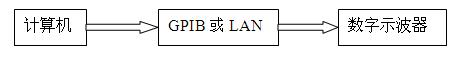
Figure 1 System hardware architecture
The computer establishes a connection with the oscilloscope through GPIB or LAN (network port) to control the oscilloscope. The hardware architecture of its system is shown in Figure 1.
2. System software architecture
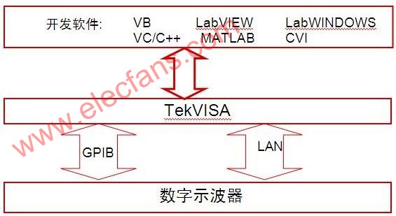
Figure 2 System software architecture
Figure 2 is a system software architecture diagram of a computer-controlled oscilloscope. The entire software development and the operating environment after software development are on the Windows operating system platform. The written application program controls the oscilloscope through TekVISA.
3. Examples of computer-controlled oscilloscope steps (taking LAN port control as an example, developing software: labview)
The following is a detailed description of how the computer programs and controls the oscilloscope.
3.1 Selection of development software
There are many most popular analysis and development software on the market, including VC / VC ++, VB / VBA, Matlab, Labview, LabWindow CVI and other development software, which are selected according to personal hobbies and familiarity with a certain software.
3.2 Install the driver
TekVISA is a VISA library developed by Tektronix and can be downloaded for free from Tektronix 'website. If it is an oscilloscope from another company, you can also use TekVISA software. After TekVISA is running, it will automatically find the LAN and GPIB interface devices connected to the network and display them in the prompt box at the same time, as shown in Figure 3. According to different IP addresses, different instruments and devices can be distinguished.
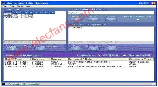
Figure 3 TekVISA automatic search instrument interface
3.3 Selection of control interface
There are many interfaces for establishing a connection between the computer and the oscilloscope, including GPIB, LAN, USB and other interfaces.
a. .LAN [TCPIP :: 192.168.0.188 :: INSTR]
b. GPIB [GPIB0 :: 1 :: INSTR]
c. USB [USB :: 0X1234 :: 125 :: A22-5 :: INSTR] (DPO4K / 3K / AFG3K)
3.4. Basic settings of oscilloscope and PC (taking LAN port as an example)
a. Set the IP address of the oscilloscope, for example: 192.168.0.168
b. Set the IP address of the PC, for example: 192.168.0.188
c. Turn off the Windows of the oscilloscope and PC and the firewall of the antivirus software
3.5 Start TekVISA and make related settings
a. Change the communication interface of the oscilloscope to LAN, as shown in Figure 4.
Figure 4 The communication interface of the oscilloscope is changed to LAN
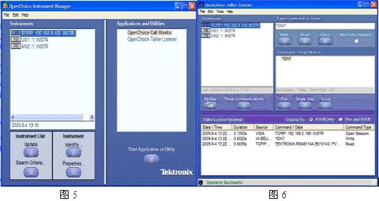
b. Open the TekVISA Instrument Manager on the PC, see Figure 5 and Figure 6, to see if the PC and the oscilloscope have established a connection and found the oscilloscope.
3.6 Start LABVIEW and start writing control program
a. Start labview, and open the Front Panel of labview, write the relevant software operation interface, see Figure 7.
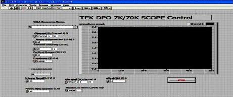
Figure 7 labview control oscilloscope software operation interface
b. Open the Block Diagram programming interface of labview to write a program to control the oscilloscope.
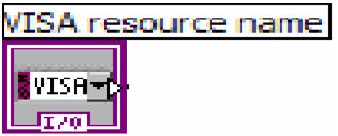
c. Create an object, see Figure 8.
Picture 8
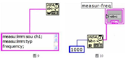
d. Set the oscilloscope parameters, according to the actual measurement needs and subsequent data processing requirements, set the oscilloscope acquisition mode, oscilloscope channel, vertical resolution, sampling rate, trigger type, record length and other parameters, and the corresponding measurement parameters. Figure 9 sets the oscilloscope's automatic measurement frequency, and Figure 10 automatically reads the oscilloscope's measured values.
e. After the oscilloscope meets the trigger conditions, collect data and display the collected data on the software interface. See Figure 11 and Figure 12.
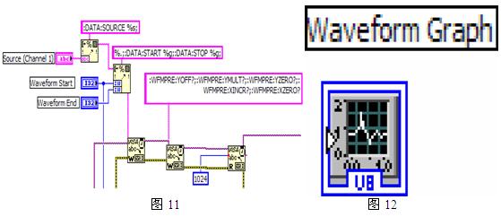
In this way, a complete labview program for controlling the oscilloscope is completed, and the engineer can add the data processing part according to his application requirements.
1. System hardware architecture
Figure 1 System hardware architecture
The computer establishes a connection with the oscilloscope through GPIB or LAN (network port) to control the oscilloscope. The hardware architecture of its system is shown in Figure 1.
2. System software architecture
Figure 2 System software architecture
Figure 2 is a system software architecture diagram of a computer-controlled oscilloscope. The entire software development and the operating environment after software development are on the Windows operating system platform. The written application program controls the oscilloscope through TekVISA.
3. Examples of computer-controlled oscilloscope steps (taking LAN port control as an example, developing software: labview)
The following is a detailed description of how the computer programs and controls the oscilloscope.
3.1 Selection of development software
There are many most popular analysis and development software on the market, including VC / VC ++, VB / VBA, Matlab, Labview, LabWindow CVI and other development software, which are selected according to personal hobbies and familiarity with a certain software.
3.2 Install the driver
TekVISA is a VISA library developed by Tektronix and can be downloaded for free from Tektronix 'website. If it is an oscilloscope from another company, you can also use TekVISA software. After TekVISA is running, it will automatically find the LAN and GPIB interface devices connected to the network and display them in the prompt box at the same time, as shown in Figure 3. According to different IP addresses, different instruments and devices can be distinguished.
Figure 3 TekVISA automatic search instrument interface
3.3 Selection of control interface
There are many interfaces for establishing a connection between the computer and the oscilloscope, including GPIB, LAN, USB and other interfaces.
a. .LAN [TCPIP :: 192.168.0.188 :: INSTR]
b. GPIB [GPIB0 :: 1 :: INSTR]
c. USB [USB :: 0X1234 :: 125 :: A22-5 :: INSTR] (DPO4K / 3K / AFG3K)
3.4. Basic settings of oscilloscope and PC (taking LAN port as an example)
a. Set the IP address of the oscilloscope, for example: 192.168.0.168
b. Set the IP address of the PC, for example: 192.168.0.188
c. Turn off the Windows of the oscilloscope and PC and the firewall of the antivirus software
3.5 Start TekVISA and make related settings
a. Change the communication interface of the oscilloscope to LAN, as shown in Figure 4.
Figure 4 The communication interface of the oscilloscope is changed to LAN
b. Open the TekVISA Instrument Manager on the PC, see Figure 5 and Figure 6, to see if the PC and the oscilloscope have established a connection and found the oscilloscope.
3.6 Start LABVIEW and start writing control program
a. Start labview, and open the Front Panel of labview, write the relevant software operation interface, see Figure 7.
Figure 7 labview control oscilloscope software operation interface
b. Open the Block Diagram programming interface of labview to write a program to control the oscilloscope.
c. Create an object, see Figure 8.
Picture 8
d. Set the oscilloscope parameters, according to the actual measurement needs and subsequent data processing requirements, set the oscilloscope acquisition mode, oscilloscope channel, vertical resolution, sampling rate, trigger type, record length and other parameters, and the corresponding measurement parameters. Figure 9 sets the oscilloscope's automatic measurement frequency, and Figure 10 automatically reads the oscilloscope's measured values.
e. After the oscilloscope meets the trigger conditions, collect data and display the collected data on the software interface. See Figure 11 and Figure 12.
In this way, a complete labview program for controlling the oscilloscope is completed, and the engineer can add the data processing part according to his application requirements.
A gas heaters is a space heater used to heat a room or outdoor area by burning natural gas, liquefied petroleum gas, propane or butane . Indoor gas heaters can be broadly categorized in flued or non-flued, or vented and unvented.
we focus on wall Gas Heater, Portable Gas Heater. Natural Gas Heater provide clean, efficient heat on cold winter. Natural gas heaters can be wall-mounted or freestanding units to suit the rooms. Ventless heaters:Ventless gas heaters, also called vent-free or no-vent heaters.
Welcome to OEM
thanks
Gas Heater
Calor Gas Heaters,Portable Gas Heater,Outdoor Gas Heater,Natural Gas Heater
Fenry manufacturing Co., Ltd , https://www.cnfenry.com