1 Introduction
Since 2005, more than 25W electronic ballasts have to have PFC, which has become a global mandatory requirement, because in that year, Europe enforced the electronic ballast power factor correction (PFC) bill.
In the past, most ICs with PFC electronic ballasts required two ICs, one of which was a PFC controller and the other IC was a half-bridge ballast controller. Developed on the IR2166 and IRS2166D, the IRS2168D is an advanced single-chip IC that combines a PFC controller with a half-bridge control/driver on the same chip. The use of IRS2168D to design fluorescent electronic ballasts can significantly reduce the number of components, reduce PCB area, reduce system cost, and has high performance and high reliability.
2 IRS2168D structure and its characteristics
The IRS2168D is available in a 16-lead PDIP lead-free package with pinouts as shown in Figure 1.
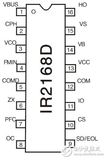
Figure 1 IRS2168D pinout
The IRS2168D chip integrates the PFC controller and the ballast controller. The internal block diagram is shown in Figure 2.
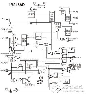
Figure 2 IRS2168D internal structure block diagram
The main features of the IRS2168D are as follows:
(1) The PFC in IRS2168D is a critical conduction mode step-up controller that provides overcurrent, overvoltage, and input undervoltage protection. It provides super-wide AC line input and multi-lamp conditions at 85-265V. Low input current total harmonic distortion (THD) and high power factor close to 1.
(2) Ballast control in the IRS2168D and 600V half-bridge driver, including voltage controlled oscillator (VCO), bootstrap MOSFET, lamp end of life (EOL) window comparator, current sense positive/countdown fault counter, Provides undervoltage lockout (UVLO), warm-up, lamp-triggered start (ie, ignition), normal operation, and fail-safe mode of operation. Protection features include half-bridge overcurrent, closed-loop ignition current regulation, EOL, lamp removal and automatic restart shutdown, and filament failure protection.
(3) Providing programmable parameters such as PFC and half-bridge overcurrent protection, warm-up time and preheat frequency, ignition ramp and operating frequency can all be set by external RC components.
(4) A 15.6V clamp Zener diode is set inside the pin VCC. The IC startup current is only about 220μA, the operating current is as low as 5.5mA, and the dead time of the two half-bridge drivers is fixed at 1.6μS. The output source current is 180mA and the sink current is 260mA.
3 Single-lamp electronic ballast circuit composed of IRS2168D
The fluorescent lamp electronic ballast circuit composed of IRS2168D is shown in Figure 3.
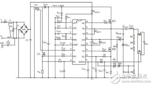
Figure 3 Electronic ballast circuit with high power factor fluorescent lamp using IRS2168D
In Figure 3, the IC (IRS2168D) pin, the pin-to-inside PFC controller, and the components external to these pins form a boost-type critical conduction mode (CRM) PFC pre-converter. Inserting this stage of PFC circuit between the half-bridge inverter and the front-end bridge rectifier can shape the AC input current into a sine wave and keep the same phase with the AC input voltage, so that the system exhibits pure resistance and achieves almost equal to 1. The power factor is generated and a 400V boosted DC regulated bus voltage VBUS is generated across the output capacitor CBUS.
The LPFC is a boost inductor whose auxiliary winding is used to sense the inductor current. As long as the inductor current reaches zero at the end of a switching cycle, it is detected by the IC pin, and the IC pin outputs a high-level voltage signal to drive the PFC switch VT3 to turn on. When VT3 is turned on, the inductor LPFC current flows through VT3 due to the turn-off diode VDPFC off. After the inductor current increases linearly from zero to the peak value, VT3 is turned off, and the VDPFC is turned on by the energy released by the LPFC, and the inductor current linearly decreases from the peak value. Once the inductor current becomes zero, VT3 turns on immediately and begins a new switching cycle. The peak inductor current of each switching cycle tracks the instantaneous change of the AC input voltage. The high-frequency triangular wave inductor current is filtered by the input capacitor C2 to obtain a sinusoidal input current proportional to the input voltage, thereby achieving power factor correction.
The resistor divider RBUS1/RBUS2 on the IC pin is used to detect the DC bus voltage. When an overvoltage or undervoltage condition occurs, the voltage on the IC pin will exceed 4.3V or below 3V and the PFC output will be disabled. The VT3 source resistor ROC is used to sense the PFC stage overcurrent. The voltage on the ROC will be disabled as long as it reaches the 1.2V threshold level inside the pin.
If the ballast output power is PO, the lowest AC line voltage is VAC (min), the PFC stage efficiency is y (typically 95%), and the peak current through the LPFC is:
 (1)
(1)
The Roc value is given by equation (2):
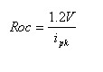 (2)
(2)
RSUPPLY on the IC pin is the startup resistor. At the time of IC startup, the capacitor CVCC1 (2.2 to 4.7 μF) is charged by the current of the startup resistor. When the voltage on the IC pin exceeds the threshold of 12.5V, the IC starts and the oscillator begins to oscillate. After the half-bridge produces an output, a charge pump consisting of CSNUB, VDCP1, and VDCP2 supplies current to the IC pin.
After the system is started, the IC oscillator first oscillates at the preheat frequency fPH. The warm-up time tPH is set by the resistor RCPH and capacitor CPH on the IC pin. The calculation formula is:
tPH=RCPHCPH (3)
In general, the warm-up time is set within the range of 0.7 to 1.5 s.
After the warm-up is over, the IC enters the ignition sequence and the frequency is shifted to the lowest oscillation frequency fmin. The ignition time TIGN is approximately 40% of the warm-up time, ie TIGN ≈ 0.4 tPH.
The ignition ramp time tRAMP is defined as the charge of the capacitor CVCO on the IC pin to 2V elapsed time. The tRAMP value is given by equation (4):
tRAMP=RPHCVCO (4)
Once the light is illuminated, the IC enters the run mode. In this mode, the oscillator frequency is lowest. The operating frequency fRUN is primarily determined by the resistor RFMIN on the IC pin. If RFMIN=42.2KΩ is selected, the operating frequency is 44.5kHz (typical). The preheating frequency is much higher than the operating frequency. The preheating frequency fPH is 85 kHz (typical) under the condition of selecting RPH = 42.2 KΩ.
The switch VT2 source resistor RCS under the half bridge is used to detect the half bridge current. Once the voltage on the IC pin exceeds the 1.2V threshold, the IC will turn off its drive output.
Connect R3, R4 and CSE2, VD1 and CSE1 on the filament at the lower end of the lamp to form the lower filament failure detection circuit. R5, R6, R7 and R8 and CEOL, VS1, VS2, CSE1, etc., constitute an EOL detection circuit. As long as the voltage on the IC pin (SD/EOL pin) is below 1V or exceeds 3V, the IC will enter the fail-safe mode.
4 Conclusion
IR's recently launched IRS2168D "two-in-one" combination IC provides a single-chip solution for designing high power factor fluorescent electronic ballasts. Like the IRS2166D, the IRS2168D has a built-in bootstrap MOSFET in a lead-free package. The difference between the two ICs is that the IRS1268D has one more PFC overcurrent detection pin (OC pin) than the IRS2166D.
The LED Indicator is a device that monitors the operation or position of an electrical device with light. The indicator light is usually used to reflect the working state of the circuit (with or without electricity), the operating state (running, outage or test) of the electrical equipment, and the position status (closed or disconnected).
In our company,mainly have eight series(as follow):
AD22-22DS LED Indicator
AD22-4SMD LED IndicatorAD16 LED Indicator
AD22-22MSD Buzzer
AD22-30DS LED Indicator
AD22-DAV Current Voltage Indicator
AD22-DAM Current Indicator
AD22-DVM Voltage Indicator
LED Indicators,LED Indicator Light,LED Indicator Lamp,LED Indicator Bulbs
Ningbo Bond Industrial Electric Co., Ltd. , https://www.bondelectro.com