Abstract: In order to overcome the shortcomings of in-vehicle embedded devices that are difficult to collect and upgrade software, a remote software upgrade method based on WiFi communication is proposed. The method effectively allocates the FLASH storage space of the microcontroller, designs the IAP function, uses the WiFi communication interface to download new software to the FLASH by using the TFTP protocol, and realizes the online upgrade of the embedded software. The detailed design and program flow of the upgrade method are given, which is fast and has little impact on the environment. The method can be applied to mobile distributed embedded devices.
This article refers to the address: http://
introduction
As system functions and performance requirements continue to increase, or to eliminate defects, users often need to upgrade embedded terminal device software. At present, embedded terminal software upgrade methods include special tool programming, system programming (ISP) and application programming (IAP). The first two methods require specialized personnel to arrive at the site or even disassemble the device for software upgrades. The IAP method can be flexibly designed by developers based on actual applications, such as serial port upgrades and USB upgrades.
Due to the mobility, wide distribution, and inability to centrally recall, the traditional software upgrade solution seems to be at a loss. The remote software upgrade solution can provide great convenience for system maintenance. At present, the mainstream uses the GPRS-based IAP method, but usually needs to pay a certain fee to the operator.
According to the actual situation of a unit vehicle management system, this paper designs a remote software upgrade method based on WiFi. It is simple, convenient, reliable, and low cost.
1 System principle
The system structure is shown in Figure 1. The unit has a number of divisions, each of which independently governs the vehicle to which it belongs, and each vehicle is loaded with a set of terminals for recording vehicle travel information. When the vehicle goes out to perform the task and returns to the gate of the yard, the data acquisition device at the door of the yard interacts with the data via WiFi. Each branch data collection device is connected to the Internet to exchange data with the headquarters.
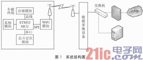
The terminal device MCU uses the STM32F107 chip, which is an ARM Cortex-M3 based 32-bit embedded processor from STMicroelectronics, with a clock speed of 72 MHz and 90 DMIPS. It has 256 KB of Flash program memory, 20 KB of data memory and 64 KB of RAM. The peripheral interface is rich, the price is only equivalent to 8-bit single-chip microcomputer, and the cost performance is extremely high.
The WiFi module uses RedPine's RS9110-N-11-02 module, which communicates with the MCU via the SPI interface. The RS9110-N11-02 module is an IEEE 802.11b/g/n WLAN device with integrated MAC, baseband processor, amplitude-adjustable RF transceiver, frequency reference and antenna. The hardware module embeds the network protocol stack, WLAN protocol and configuration functions to form a complete 802.11n WLAN solution.
The system software upgrade process is as follows:
1 Transfer the compiled new software to each branch data acquisition device via Ethernet;
2 When the vehicle goes out or returns, it passes through the WiFi network coverage area of ​​the data acquisition device at the gate of the yard;
3 The vehicle terminal device is connected to the data collection device through the WiFi network, and if necessary, a new software download is performed;
4 The vehicle terminal executes the new software.
2 software upgrade method and process
The internal FLASH memory address of STM32F107 starts at 0x08000000 with a total of 256K. In order to upgrade online, the FLASH memory is divided into a BOOT area, an application area, a temporary area, and a parameter storage area as shown in FIG. 2 .
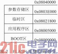
The BOOT area is used to store the system bootloader, the application area is used to store the user application software, the temporary area is used to temporarily store the software being downloaded, and the parameter storage area is used to store the logo and other system parameters used in the program upgrade.
The software upgrade flags are defined as follows: normal mode, upgrade mode, and copy mode. The normal mode marks that there is no need to upgrade the software and jumps directly to the application area to execute; the upgrade mode indicates that the terminal needs to download a new application; the copy mode is used to copy to the application area after the software is downloaded, and the part is functionally independent. It comes out in order to recover from a failure such as a sudden power failure when copying to the application area after the software is downloaded.
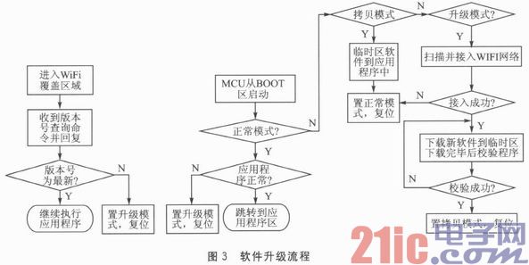
When the terminal is in the WiFi signal range, the WiFi network is connected to the data collection device for information interaction. As shown in Figure 3, the software upgrade process is as follows:
1 Receive the version number query instruction, and reply the software version number of the terminal to the data collection device;
2 If the version number is the latest, the process ends, otherwise it will receive the software upgrade instruction sent by the data acquisition device;
3 Modify the software upgrade flag stored in the parameter storage area to upgrade mode, reset the MCU;
4MCU is started from the BOOT area;
5 Read the software upgrade flag, if it is "normal mode", determine whether there is an application in the application area, if any, jump to the application area to execute, if not, then set the software upgrade flag to "upgrade mode", reset MCU, jump Go to step 4;
6 If the software upgrade flag is "copy mode", copy the temporary area software to the application area, modify the software upgrade flag to the normal mode, reset the MCU, and jump to step 4;
7 If the software upgrade flag is “upgrade modeâ€, scan and access the WiFi network;
8 Use the TFTP protocol to download new software to the temporary area;
9 Verify that the new software is correct. If it is not correct, go to step 8. If it is correct, execute the next step.
10 Modify the software upgrade flag to “copy modeâ€, reset the MCU, and go to step 4.
3 software implementation
The upgrade software mainly consists of version number comparison, software reset, software download and verification, copy software to the application area, and software jump to the application area.
(1) Comparison of version numbers
Each version of the software needs to have different version numbers and increment according to certain rules. For example, if the software version 2.0 on the data collection device is higher than the version 1.0 of the terminal, the software upgrade is performed accordingly.
(2) Software reset
According to this design, the software needs to be reset into the BOOT area for a series of operations. Software reset is achieved by setting the STM32 internal interrupt application and the SYSRESETREQ bit in the Reset Control register.
(3) Software download and verification
Use the TFTP protocol to download the application software to the MCU temporary area. TFTP is simple to implement and has high reliability when it is used to send smaller files. The lower layer uses the UDP protocol and sends the port using UDP 69. The maximum packet sent each time is 512 bytes, and both sides use the timeout retransmission mechanism. The data transmission mode can be selected as octet mode (binary mode).
TFTP supports 6 types of data packets, which are:
1Read rcquest(RRQ);
2Write rcquest(WRQ);
3Data(DATA);
4Acknowledgment(ACK);
5Error(ERROR);
6OACK.
Currently used are the top five. Since the system only needs to implement the terminal to download the software file from the data collection device, it is not necessary to implement the complete TFTP protocol, and only the first, third, fourth, and fifth types of data packet functions can be implemented. Mainly define the following four interface functions:
1RRQ send interface function definition:
Void tftpReadQuerry(void);
The function is used by the terminal to send a read file request, and the data collection device receives the packet to send a file data packet to the terminal;
2 packet receiving interface function definition:
Void tftp_recvpacket(void);
The function is used to receive the packet sent by the data collection device, and process the ERROR packet and the DATA packet according to the packet type. If it is an ERROR packet, the file needs to be retransmitted, and the transfer fails. If it is a DATA packet, it is stored according to the package number to the specified location of the FLASH, and then the ACK function is called to reply ACK. Error handling of dropped packets, error packets, etc. is also performed in this function;
3ACK send interface function definition:
Void tftpSendAck(unsigned char BlockNo[2]);
This function is used to reply to an ACK based on the number of the received packet.
4ERROR package interface function definition:
Void tftpSendErr(unsigned char BlockNo[2]);
This function is used to return a transmission error message.
The file transfer implementation process is as follows:
1 The data collection device waits for the terminal to issue a read file request packet on the UDP port 69;
2 The terminal sends an RRQ packet conforming to the TFTP request format to the data collection device through UDP;
After receiving the request packet of the terminal, the data collection device will directly send the DATA packet to the terminal. The DATA packet includes the TID selected by the data collection device as the source port of the UDP and the TID of the terminal as the UDP target port, and the starting packet number. It is 1, and the subsequent package number is incremented by 1.
4 The terminal receives the DATA packet from the data acquisition device and replies with an ACK. Until the request is completed.
A packet loss or packet error during transmission will result in retransmission and no more than three retransmissions. Otherwise, the transmission is considered to have failed. An error during transmission will trigger the sending of an ERROR packet. The error code value of the ERROR package is for analysis by the programmer.
(4) copy the software to the application area
After the software is correctly downloaded to the temporary area, it needs to be copied to the application area. The key part of this part is the erasing and reading and writing of FLASH embedded in STM32.
STM32F107 embedded FLASH is through the paging mechanism to achieve the expansion of the addressing space and the use and management of FLASH pages. Therefore, the erase operation of FLASH needs to be erased by page. That is, erasing FLASH cannot erase a certain byte or erasing less than one page (2048 bytes) at a time.
The specific steps of FLASH erasure:
1 unlock the FLASH programming control register;
2 locating the sector to be erased;
3 write sector erase command;
4 waiting for the command to complete;
5 Lock the FLASH programming control register.
The steps to write to FLASH are as follows:
1 unlock the FLASH programming control register;
2 write a number of words of data to the specified address;
3 Wait for the previous command to be executed;
4 If the data has not been written, increment the source address and the target address, repeat steps 2 and 3;
5 Lock the FLASH programming control register.
(5) Software jump application area
After the application is ready, the program needs to jump from the BOOT area to the first address of the application area to execute the application. Here are two steps:
1 Modify the interrupt vector table location. Since the STM32F107 uses the ARM Cortex-M3 core, the register address NVIC_VectTaD_Addr of the write interrupt vector table in the system control space of the core is 0xE000ED08, and the application start address can be written at this address. The program application start address APP_START_ADDRESS is 0x08005000. The design is as follows:
Ldr r0,=0x08005000
Ldr r1,=0xe000ed08
Str r0, [r1]
2 Jump to the application's first address to execute the application. This step completes the modification of the stack pointer and program pointer (PC). After the above assembly code, it is implemented as follows:
; load the stack pointer from the application vector table
Ldr r1, [r0]
Mov sp,r1
; initialize the program pointer (PC) from the application vector table and jump to the application
;Entrance
Ldr r0, [r0,#4]
Bx r0
In order to ensure that the software upgrade error does not cause the system to crash, the terminal program is isolated as the boot program (BOOT area program) and the application program. If the single software upgrade fails, the terminal program can be upgraded again. The two parts of the program are compiled in Keil, and the BOOT area program is programmed at the first address of the FLASH 0x08005000, so that the terminal can directly enter the BOOT area. For application compilation, you need to set the programming address to the first address of the application area, and generate a bin file for direct download to FLASH to run.
Conclusion
The method realizes the function of downloading the compiled software file to the terminal device through the TFTP protocol by using the WiFi communication mode, and completing the software upgrade function. In the field of embedded systems, program upgrades can easily compensate and modify program defects, or expand program functions. This method can greatly improve product life cycle, save project maintenance costs and improve development efficiency.
Based on this method, a vehicle management system capable of remote online upgrade program has been successfully designed. The usage shows that the system can work stably and reliably, and saves a lot of work for the maintenance of the system. It has a good reference value for the online upgrade of the same type of embedded device software.
- STM32 microcontroller Chinese official website
- STM32 microcontroller official development tools
- STM32 microcontroller reference design
BBQ Grill,Fashion Barbecue Grill,Stainless Steel Grill,Smokeless BBQ Grill
Shaoxing Haoda Electrical Appliance Co.,Ltd , https://www.hotplates.nl