With the emergence and widespread popularity of electronic design, computers and household appliances, grid noise interference has become increasingly serious and has become a public hazard. In particular, transient noise interference has a fast rising speed, a short duration, a high voltage amplitude (several hundred volts to several thousand volts), and strong randomness, which is liable to cause serious interference to microcomputers and digital circuits, and often prevents people from being prevented. Has attracted the attention of the electronics industry at home and abroad. Electromagnetic interference filter (EMI Filter) is a new type of combined device that has been popularized and applied in recent years.
It can effectively suppress the noise of the power grid, improve the anti-interference ability of electronic equipment and the reliability of the system. It can be widely used in electronic measuring instruments, computer room equipment, switching power supply, measurement and control systems and other fields.
1 Construction principle and application of electromagnetic interference filter
1.1 Construction principle
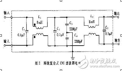
Figure 2 shows the internal circuit of a two-stage hybrid EMI filter. Since two-stage (also called two-section) filtering is used, the effect of filtering noise is better. For some users, there is a problem of fast transient group pulse interference with a repetition frequency of several kilohertz. A group pulse filter (also known as a group pulse antagonist) has been developed at home and abroad, which can suppress the above interference.
Power supply noise is a type of electromagnetic interference, and its conducted noise spectrum is approximately 10 kHz to 30 MHz, up to 150 MHz. Depending on the direction of propagation, power supply noise can be divided into two categories: one is external interference introduced from the power supply line, and the other is noise generated by the electronic device and conducted out through the power line.
This indicates that the noise belongs to the two-way interference signal, and the electronic device is both the object of noise interference and a noise source. According to the formation characteristics, noise interference is divided into two types: serial mode interference and common mode interference. Serial mode interference is the noise between two power lines (referred to as line-to-line). Common mode interference is the noise of two power lines to the ground (referred to as line to ground).
Therefore, the electromagnetic interference filter should meet the requirements of electromagnetic compatibility (EMC), and must also be a two-way RF filter. On the one hand, it should filter out the external electromagnetic interference introduced from the AC power line, on the other hand, it can avoid the device itself. External noise is emitted to avoid affecting the normal operation of other electronic devices in the same electromagnetic environment. In addition, the EMI filter suppresses both serial mode and common mode interference.
1.2 Basic circuit and its typical application
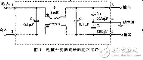
The basic circuit of the electromagnetic interference filter is shown in Figure 1.
The five-terminal device has two inputs, two outputs, and a ground terminal. When used, the case should be connected to the ground. The circuit includes a common mode choke (also known as common mode inductor) L and filter capacitors C1 to C4. L does not work on series mode interference, but when common mode interference occurs, since the magnetic flux directions of the two coils are the same, the total inductance increases rapidly after coupling, so the common mode signal exhibits a large inductive reactance. It is not easy to pass, so it is called a common mode choke.
Its two coils are wound around a low-loss, high-permeability ferrite magnetic ring. When a current is passed, the magnetic fields on the two coils reinforce each other. The inductance of L is related to the rated current I of the EMI filter, see Table 1. It should be pointed out that when the rated current is large, the wire diameter of the common mode choke coil should be correspondingly increased to withstand a large current. In addition, by appropriately increasing the inductance, the low-frequency attenuation characteristics can be improved.
C1 and C2 use film capacitors with a capacitance range of approximately 0.01μF to 0.47μF, which is mainly used to filter out series mode interference. C3 and C4 are connected across the output and ground the capacitor at the midpoint, effectively suppressing common mode interference.
C3 and C4 can also be connected in parallel at the input end, still using ceramic capacitors, the capacity range is 2200pF ~ 0.1μF. To reduce leakage current, the capacitance must not exceed 0.1μF and the midpoint of the capacitor should be connected to ground. The pressure values ​​of C1 to C4 are both 630 VDC or 250 VAC.
2 EMI filter application in switching power supply
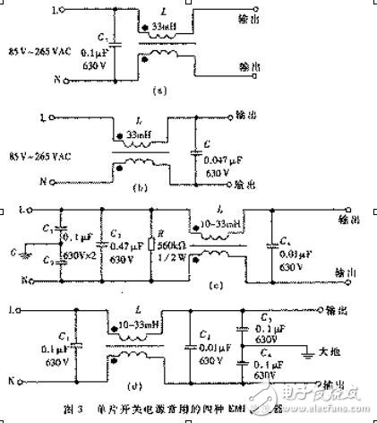
In order to reduce the size and reduce the cost, the single-chip switching power supply generally adopts a simple single-stage EMI filter. The typical circuit is shown in Figure 3. The capacitor C in Figure (a) and Figure (b) can filter the serial-mode interference. The only difference is that Figure (a) connects C to the input and Figure (b) to the output.
The circuits shown in (c) and (d) are more complicated and the effect of suppressing interference is better. L, C1 and C2 in Figure (c) are used to filter out common mode interference, and C3 and C4 are filtered out to avoid series mode interference. R is a bleeder resistor, which can discharge the accumulated charge on C3 to avoid the filter characteristics due to charge accumulation. After the power is off, the incoming end L and N of the power supply can be de-charged to ensure the safety of use. Figure (d) shows the common mode interference filter capacitors C3 and C4 connected to the output.
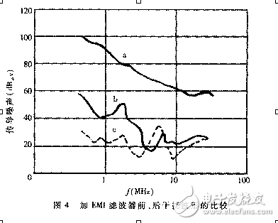
The EMI filter can effectively suppress the electromagnetic interference of the single-chip switching power supply. The curve a in Fig. 4 is a waveform of 0.15 MHz to 30 MHz conducted noise on the switching power supply when the EMI filter is applied (i.e., the electromagnetic interference peak envelope). The curve b is a waveform obtained by inserting an EMI filter as shown in Fig. 3(d), and can attenuate electromagnetic interference by 50 dBμV to 70 dBμV. Obviously, this EMI filter works better.
3 EMI filter technical parameters and test methods
3.1 Main technical parameters
The main technical parameters of EMI filter are: rated voltage, rated current, leakage current, test voltage, insulation resistance, DC resistance, operating temperature range, working temperature rise Tr, insertion loss AdB, external dimensions, weight, etc. The most important of the above parameters is the insertion loss (also known as the insertion attenuation), which is the main indicator for evaluating the performance of the EMI filter.
Insertion loss (AdB) is a function of frequency and is expressed in dB. It is assumed that the noise power transmitted to the load before and after the insertion of the electromagnetic interference filter is P1 and P2, respectively, and there is a formula:
AdB=10lg(P1/P2) (1)
Assuming that the load impedance remains constant before and after insertion, P1 = V12 / Z, P2 = V2 2 / Z. Where V1 is the voltage directly applied to the load by the noise source, and V2 is the noise voltage on the load after the EMI filter is inserted between the noise source and the load, and V2 is obtained in the equation (1).
AdB=20lg(V1/V2) (2)
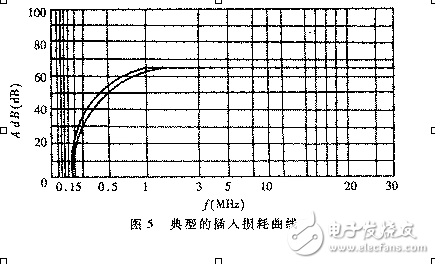
The insertion loss is expressed in decibels (dB). The larger the decibel value, the stronger the ability to suppress noise interference. In view of the cumbersome theoretical calculations and large errors, the actual measurement is usually performed by the manufacturer, and the corresponding insertion loss is measured point by point according to the noise spectrum, and then a typical insertion loss curve is drawn and provided to the user. Figure 5 gives a typical curve. As seen from the curve, the product can attenuate the noise voltage from 1MHz to 30MHz by 65dB.
The formula for calculating the EMI filter to ground leakage current is:
ILD=2Ï€fCVc (3)
Where, ILD is the leakage current and f is the grid frequency. Taking Figure 1 as an example, f=50Hz, C=C3+C4=4400pF, Vc is the voltage drop across C3 and C4, that is, the voltage to the ground of the output terminal, which can be Vc≈220V/2=110V. It is not difficult to calculate from equation (3). At this time, the leakage current ILD is 0.15 mA. If C3 and C4 are 4700pF, then C=4700pF&TImes; 2=9400pF, ILD=0.32mA. Obviously, the leakage current is proportional to C. The requirement for leakage current is as small as possible, so that the safety is high, and generally should be several hundred microamperes to several milliamps. The requirements for leakage current in electronic medical equipment are more stringent.
It should be noted that the rated current is also related to the ambient temperature TA. For example, some foreign manufacturers give the following empirical formula:
I=I1&TImes;[(85-TA)/45 root number 2 power]
In the formula, I1 is the rated current at 40 °C. For example, when TA = 50 ° C, I = 0.88 I1; and when TA = 25 ° C, I = 1.15 I1. This indicates that the rated current value increases as the temperature decreases, which is due to the improvement in heat dissipation conditions.
3.2 Method of measuring insertion loss
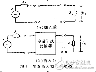
The circuit for measuring the insertion loss is shown in Figure 6. e is the noise signal generator, Zi is the internal impedance of the signal source, and ZL is the load impedance, which is generally 50Ω. The noise frequency range is from 10kHz to 30MHz.
Firstly, the noise voltage drops V1 and V2 on the load before and after insertion are measured at different frequencies, and then the AdB value of each frequency point is calculated by substituting (2), and the insertion loss curve is finally drawn. It should be pointed out that the above test method is cumbersome, and the EMI filter must be disassembled every time. For this purpose, the electronic switches can be used to quickly switch between the two test circuits.
Closed Pod Vape,Pod Vape System,Rechargeable E Cigarette,Rechargeable E-Cigarette Vape Pen
ALD GROUP LIMITED , https://www.aldvapor.com