1 Introduction
The flexible spatial layout and design freedom of the free-form surface not only improves the image quality of the optical system in the imaging optics, but also redistributes the light source intensity in the illumination system to facilitate the flexible design of the light distribution curve. Although the free-form surface design of the light distribution curve is simple and practical, in the face of the complex mathematical relationship in the free-form surface design process, many designers can only hope to sigh. In this paper, the mathematical derivation process of establishing partial differential equations suitable for light distribution design is demonstrated in detail, and an explicit expression of a generalized partial differential equations is obtained. The trapezoidal method of differential equation initial numerical solution is used to solve one. A free-form surface characteristic curve of a rotationally symmetric LED lens.
2. Establishment of mathematical models
2.1 Definition of coordinate system
The spatial luminosity data of the luminaire usually adopts three coordinate systems: A-α, B-β and C-γ. The C-γ coordinate system has a 4π spheroidal space, which tends to be A-α, B-β than the 2π spheroidal space. The coordinate system is more widely used. In the three-dimensional Cartesian coordinate system shown in Figure 1, the point source is located at the origin O of the coordinate system. The light emitted from the origin O reaches any point O' on the free surface, and is reflected or refracted to the point R by the free surface. OO' is the incident ray vector, and O ' R is the reflected or refracted ray vector.
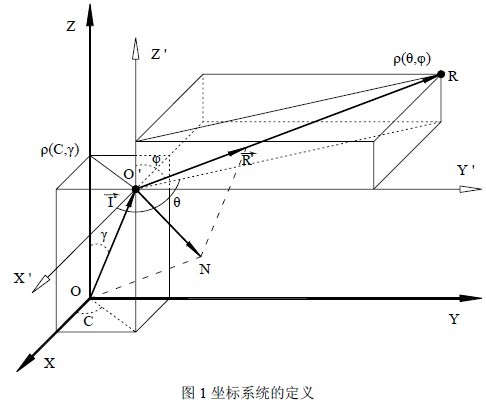
In Fig. 1, if the coordinate origin O of the Cartesian coordinate system is the center of the C-γ spherical coordinate system, any point O' on the free curved surface can be expressed as Ï(C, γ), and the angle C is the vector OO ' The angle between the projection on the XOY plane and the positive direction of the X-axis, the angle γ is the angle between the vector OO ' and the positive direction of the Z-axis; if the point O' is the center of the spherical coordinate system, the reflected ray vector O ' R It can be expressed as Ï(θ, φ), where the angle θ is the angle between the projection of the vector O ' R on the XOY plane and the positive direction of the X axis, and the angle φ is the angle between the vector O ' R and the positive direction of the Z axis. Assume that the point O' is an arbitrary point on the free-form surface, which can be expressed as O(x, y, z) in the three-dimensional Cartesian coordinate system and Ï(C, γ) in the spherical coordinate system. 1) Established.
2.2 Mathematical expression of incident ray
The incident ray vector OO ' can be expressed as an algebraic expression (2) of the vector according to the coordinates of O(x, y, z). If the formula (1) is brought into (2), the formula (3) can be obtained. In the direction of the light, it is more convenient to use the unit vector I o of the incident ray to indicate the direction of the incident ray, and the mathematical expression (4) of the unit vector I o can be obtained by the formula (3).
2.3 Mathematical expressions of reflected or refracted rays
Similar to the incident ray vector, the reflected ray vector O ' R can be expressed as an algebraic expression (5) according to the coordinates of O(x, y, z) and R(x', y', z'), and can also be expressed as a pole. The coordinate expression Ï(θ, φ), the conversion relationship between the two can be obtained by the formula (6), and the formula (6) is brought into (5) to obtain the formula (7). If only the direction of the reflected or refracted light is considered, it is more convenient to use the unit vector R o to indicate the direction of the reflected or refracted ray. The mathematical expression (8) of the unit vector R ° can be obtained by the formula (7).
2.4 Mathematical expressions of normal vectors
The incident ray and the reflected ray are symmetric about the normal amount at any incident point on the free-form surface, and the incident ray satisfies the law of refraction between the incident point and the refracted ray and the normal vector, and therefore, any point normal vector N on the free-form surface It can be represented by the unit vector I° of the incident ray and the unit vector R° of the reflected ray. Figure 2-A shows the geometric relationship between the incident ray, the reflected ray and the normal vector, and the normal vector can be subtracted from the reflected ray unit vector. The incident light unit vector is obtained; Figures 2-B and 2-C show the geometric relationship between the incident ray, the refracted ray and the normal vector. When the light enters the air from the glass, the normal vector is equal to the refracted ray unit vector to reduce the refractive index of the glass. The vector after n is subtracted from the incident ray unit vector; when the ray enters the glass from the air, the normal vector is equal to the refracted ray unit vector minus the incident ray unit vector to reduce the refractive index n times the glass.
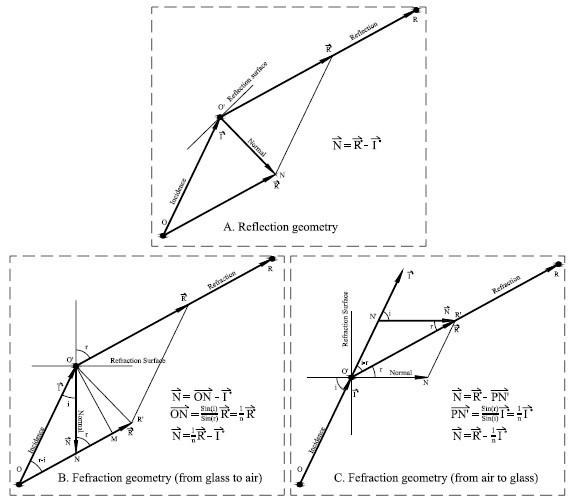
Fig. 2 Relationship between normal vector and reflected light, refracted light and incident light
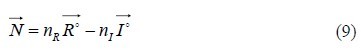
When not paying attention to the size of the normal vector and only paying attention to its direction, the above three cases can be uniformly represented by the formula (9). R n in the formula is the refractive index in the medium where the refracted (or reflected) ray is located, and I n is the incident ray. The refractive index in the medium.
2.5 mathematical expression of the cut vector
If there are two points Ï1( x1, y1 , z1 ) and Ï2 ( x2, y 2, z2) in the neighborhood σ of any point P on the surface of the reflection (or refraction), the light from the origin of the coordinate points to these two points The incident ray is represented by vectors I1 and I2, respectively, and its algebraic expressions are shown in equations (10) and (11). If the neighborhood is small enough, the difference between the two vectors I1 and I2 is the tangent vector T of the reflector surface, ie the tangent vector can be expressed by equation (12).

Bringing the formulas (10) and (11) into the formula (12) has the formula (13), where Δx, Δy, Δz represents the line between the two points in the neighborhood σ of the point P on the free-form surface at X, Y, Projection on the Z coordinate axis.

It is assumed that the free-form surface of the reflector is continuously guided in the domain of the definition. When σ → 0, Δx, Δy, Δz can be represented by the partial derivative of the point P on the surface of the reflector in the X, Y, and Z directions of each coordinate axis. Come out, there is a formula established.