Radio frequency identification technology (RFID) is a new type of automatic identification technology. Its working principle is to perform two-way data communication through wireless methods to achieve the purpose of transmitting radio frequency information. Under normal circumstances, RFID systems consist of electronic tags, readers and related application software. Among them, the tag includes the antenna and the chip in two parts. Since RFID tags and readers do not need to contact each other to complete the identification of both, the RFID system can work in various environments and can identify multiple moving targets at the same time. So far, RFID systems have been widely used in many fields, such as: logistics management, manufacturing, library management, identification, automatic road pricing and other fields.
In the RFID system communication process, the reader sends a radio frequency signal of a certain frequency through its own antenna. When the tag enters this area, the tag antenna obtains the command of the corresponding reader from the radiation field in the field, processes the tag, and then sends its own coded response information through its own antenna. The sent information is read by the reader, decoded, and then transmitted to the corresponding application system software for processing, so as to achieve the purpose of automatically identifying the object. As one of the basic components of the RFID system, the tag antenna will directly affect the accuracy of the tag reception and the transmitted signal, so it is of great significance to its research.
1 UHF RFID Tag Antenna Design Theory Principle 1.1 Impedance Conjugate MatchingThe electronic tag needs to obtain electromagnetic wave energy from the reader antenna to respond to the tag chip. Therefore, there is a small part of the electronic tag chip used to detect the induced electromotive force or induced voltage on the tag antenna, and is rectified by the diode circuit and then amplified by the voltage. , and finally read the tag information. The antenna design does not need to know the internal structure of the chip. It only needs to know the size of the chip impedance after the chip is packaged, and then uses the maximum energy transfer rule to design the antenna. The input impedance of the tag chip is divided into two parts: a resistive component and a reactive component. The reactive component is generally a capacitive impedance. In order to achieve maximum energy transfer, the input impedance of the electronic tag antenna needs to be conjugated with the input impedance of the tag chip. The input impedance of the tag chip is in the form of Z=R-jX. In order to achieve conjugate matching between the chip and the antenna, the input impedance of the antenna to be designed should be Z=R+jX. For the UHF band tag antenna, a conjugate matching structure that can introduce inductive reactance for the tag antenna is used to achieve matching between the tag chip and the tag antenna. It is generally necessary to add an annular structure to the antenna to feed additional structures or other structures for matching. In this paper, the power reflection coefficient is used to describe the impedance conjugation between the tag antenna and the tag chip.
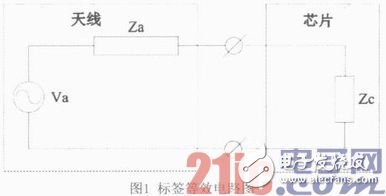
Figure 1 shows the equivalent circuit diagram. Among them Za is the input impedance of the aerial, Zc is the input impedance of the chip, Zc =Rc+jXc.
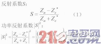
In terms of the main performance of the RFID tag antenna, the identification distance r of the tag is an important indicator parameter. The expression is as follows:
In the above formula, P1 is the transmitting power of the reader, GT is the gain of the reader antenna, the gain of the Gr tag antenna is the reflection coefficient, and Pth is the threshold power of the excitation tag chip.
1.3 Small size, low costBecause the label needs to be affixed to the corresponding item, the electronic label needs to be small enough. With the continuous development of the RFID system, the wider the label application is, the lower the production cost requirement of the electronic label is.
2 UHF RFID tag antenna design processFirst, determine the approximate structure of the antenna based on the radiation characteristics. Then, adjust the antenna structure so that the gain meets the requirements. Finally, adjusting the matching structure to match the impedance of the antenna and the chip mainly includes the following two aspects. First, adjust the size of the matching structure and summarize the effect of size on the impedance. Second, the reflection coefficient S11 "-10dB in the band, China's UHF RFID band: 840 ~ 845MHz and 920 ~ 925MHz.
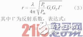
3 UHF RFID tag antenna design and HFSS simulation and result analysis 3.1 UHF RFID tag antenna designAccording to the tag antenna design theory, the chip impedance is 20-188jΩ and the operating frequency is f0=920MHz. The antenna designed in this paper uses FR4 medium with a thickness of 0.8mm and a dielectric constant of 4.6 as its substrate, and the patch is copper skin. The antenna structure is shown in Figure 2. The parameter values ​​are shown in Figure 3.
It can be seen from the structure diagram that the tag antenna adopts an electromagnetic coupling feeding structure and is composed of two parts. One is an independent bent radiator and the other is a feeding loop. The chip is excited from the opening of the feed ring. By analyzing the design theory of tag antenna, the parameter distance d in the structure and the size of its feed ring are changed to affect the coupling degree between the two, and then the impedance value of the tag antenna reaches the conjugate matching with the impedance of the tag chip.
3.2 Antenna Simulation and Result AnalysisThrough the analysis and simulation of each parameter, the effect of different values ​​of the parameters on the performance of the antenna is compared, so that the optimum value is selected and optimized. The final simulation results are shown in FIG. 4 .
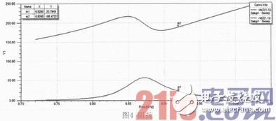
It can be seen from FIG. 4 that in the case of the frequency f0=920 MHz, the impedance is 20+188 jΩ, and the reflection coefficient S11 is −28 dB, a good conjugate matching with the tag chip impedance is completed.
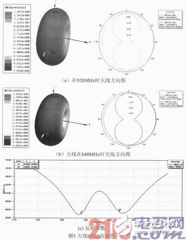
From Fig. 5(a)(b), the directivity of the antenna is omnidirectional. At f0 = 920 MHz, the tag antenna gain is 1.9 dB. The antenna has two resonance peaks near 840 MHz and 925 MHz. The electronic tag antenna has a bandwidth of -160dB at 160MHz, which is a wide band. The frequency band not only covers the target of the 840-960 MHz frequency band design, but also increases the upper frequency band by 40 MHz.
4 ConclusionThis paper designs an RFID tag antenna that works directly on the UHF band. The simulation results of the antenna show that the antenna has good impedance matching characteristics with a specific chip. The tag antenna has good radiation characteristics and can basically meet the requirements of practical applications. The structure of the antenna is simple, and the manufacturing materials used greatly reduce its production cost. Due to the small size and thin film characteristics of the antenna, the tags produced by the antenna can be widely affixed to flat objects, which can promote the wide application of RFID technology in the Internet of things. In most cases, the tag antenna in the RFID system needs to work in different environments. In many practical applications, the tag antenna needs to be attached to the surface of a high-conductivity object. Due to the boundary condition of the high-conductivity object, the distance and radiation of the tag are recognized. Parameters such as efficiency, input impedance and gain are greatly affected. In order to solve the above problems, an inverted-F antenna or planar inverted-F antenna antenna is proposed. Because in order to realize its function, the inverted-F antenna and the planar inverted-F antenna itself need a metal ground plate, which needs improvement.
Heat Resistant Braided Sleeving
Expandable braided sleeves is ideal for a limitless number of electronic, automotive, marine and industrial wire management and bundling applications. Examples include engine compartment dress up, home theater wire management, customizing computer case wiring, office wire management, automotive harnesses, scuba hose protection, and many more. Threads of different colors and textures could be braided into different patterns. Each of our products is tailored to the client's business and needs.
PET polyester Expandable Braided Sleeving is flame-retardant and halogen-free. It offers durable abrasion resistance in a wide range of industrial applications. The open weave construction allows an easy installation on a bundle of hoses and cables, even if some with bulky or large connectors.
Totally expanded the sleeving can reach at least one point five times than the initial dimension.
PET expandable braided sleeve compiled by the Environmental Protection PET filament diameter monofilament 0.20mm or 0.25mm's made with good flexibility, flame resistance, abrasion resistance and heat resistance, network management can be easily expanded to the original 150% , and it is easy to tighten the various irregularly shaped objects, which can be maintained within a wide temperature range while maintaining a soft, can inhibit chemical corrosion, UV and friction, characterized by its unique mesh also has good ventilation, wire heat diffusion function in a timely manner.
Pet Braided Cable Sleeve,Expandable Braided Sleeving ,Expandable Wire Sleeve For Cable,Braided Expandable Sleeve
Shenzhen Huiyunhai Tech.Co.,Ltd , https://www.hyhbraidedsleeve.com