introduction
This article refers to the address: http://
In China, digital TV programs have been piloted in many provinces and cities. Since the user terminals are basically analog TV sets and cannot receive digital signals, a receiving device is needed to serve as a bridge between the two. This is the set-top box ( Set Top Box, referred to as STB). It is a new type of home appliance that extends the capabilities of televisions. It can convert digital signals from satellite live digital TV signals, terrestrial digital TV signals, digital signals from cable television networks and even the Internet into analog TV-receivable signals, enabling existing analog TV users to share the digital revolution. Technological Achievements. This article mainly introduces the DVB-C-based cable digital TV set-top box developed by the author.
Hardware Design of DVB-C Digital Set Top Box
LSI 2005 main chip introduction
The DVB-C digital set-top box uses LSI Logic's SC2005 as the main chip. The SC2005 uses the latest 1.27mm PBGA package to integrate the LSIL641x8 transport decoder and L64105MPEG-2 audio and video decoder in a single chip. It has a high integration, built-in industry standard Tiny RISC108MHz MIPS CPU, 5-layer graphics engine, DMA controller. And unified OSG memory and A/V memory; integrated multi-standard encoder, independently programmable video DAC, audio DAC.
After receiving the TS stream from the channel decoder, the SC2005 sends it to the internal L641x8 module, and the data is demultiplexed by the L641x8 to form audio and video PES packet data, which is output to the L64105 MPEG-2 decoder for decoding through the A/V interface. . The L64105 decodes the PES packets and outputs two sets of digital video and digital audio signals. A set of digital video and a set of digital audio signals are output directly. Another set of digital video signals is sent to the video encoder and converted to full TV signal (CVBS) or S-terminal signal (Y/C). After external low-pass filtering, it can be sent directly to the TV. The other digital audio signal is sent to the audio DAC, converted into a stereo analog signal, and outputted by external low-pass filtering.
The SC2005 provides a variety of peripheral interfaces, including two UART interfaces, two smart card interfaces, an I2C interface, an IEEEl284 interface, an infrared interface, a teletext interface, general purpose I/O control, and a modem interface. Through these interfaces, the SC2005 can be connected to a variety of peripherals and is more powerful. In addition, SC2005 also has a hard disk interface, you can download the program to the hard disk, and then look at it later.
Overall hardware design of DVB-C set-top box
In order to realize the function of the wired digital set-top box, the following requirements must be met in terms of technical implementation:
(1) Receive radio frequency signals in the frequency range of 110 MHz to 855 MHz on the CATV network, and convert them into intermediate frequency signals.
(2) Implement the QAM demodulation function to restore the modulated signal to a digital baseband signal.
(3) Completing the channel decoding process to implement the forward error correction function.
(4) Complete TS transport stream demultiplexing, MPEG-2 decoding function, and realize TV signal decoding and audio DAC function, and output analog audio and video signals that meet the requirements.
This design implements all of the above functions, and the overall design block diagram is shown in Figure 1.
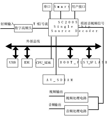
Figure 1 SC2005 set-top box system block diagram
System component function introduction
1. Digital tuner: receiving the RF signal on the CATV cable, the RF signal is down-converted to the intermediate frequency signal by the high-frequency head circuit, and the intermediate frequency signal is sent to the internal demodulation chip, and the QAM demodulation is completed by the demodulation modulation chip. And the FEC forward error correction chip, and then the TS (transport stream signal) is sent in parallel or serially.
2. SC2005: Transport stream processing chip of LSI logic.
3. CPU_SDRAM: Provides the storage space required for the SC2005 embedded CPU to run.
4. AV_SDRAM: Provides the storage space required for the internal MPEG decoder of SC2005 to process the PES stream.
5, BOOT_FLASH: store the system BOOT program, the boot system starts normally.
6, SYS_FLASH: store system work software to achieve system functions.
7. Serial port: The serial port module circuit performs level conversion on the serial I/O port of SC2005, provides standard RS232 serial interface, and provides RS232 debugging interface.
8, SMARTCARD: to achieve authorization, encryption, charging and other functions.
9, user interface: provide users with simple output, input interfaces, such as system work status display interface, button interface, remote control interface.
10, USB: Provide users with a USB 1.1 compatible interface, the highest data rate of 12Mb / s; can be used to support U disk, save programs or play programs on the U disk.
11, IDE: Provide users with a standard IDE interface. After the hard disk is attached, it can be used to save programs or play programs on the hard disk.
Software Design of DVB-C Digital Set Top Box
Overall design of software for DVB-C set-top box
The DVB-C set-top box software implementation is designed based on the principles of stability, reliability and scalability. All software systems should be fully functional, easy to use and easy to expand. According to the above analysis, the set-top box software architecture is shown in Figure 2.
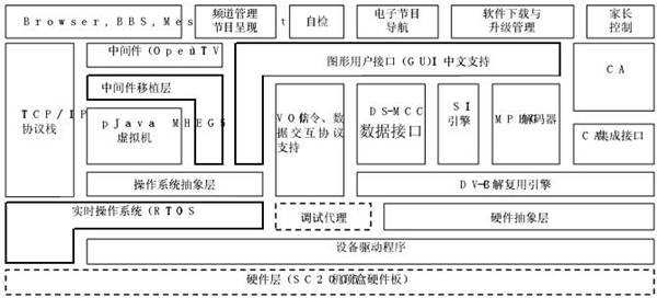
Figure 2 Set-top box software module level diagram
The structure of the entire set-top box software adopts an open modular structure. The hardware abstraction layer can increase the hardware independence of the software; the operating system abstraction layer is used to implement the portability of the operating system layer to support multiple RTOSs; the middleware porting layer is used for the transplantation of various commercial middleware software. Looking from the bottom up, the whole system is divided into the following levels from the hardware layer to the application layer:
1. Hardware abstraction layer: By refining some hardware operation features, abstracting some hardware-related operations, thus separating the operating system and hardware layer, which makes the design of BSP and Driver more concise, which is beneficial to improve the software. Reusability and portability.
2. BSP layer: used to boot the operating system and provide board-level support for the operating system. At the same time provide some near device drivers.
3, operating system and hardware driver layer: provide operating system kernel and hardware drivers. The operating system mainly provides functions such as memory management, task scheduling, clock management, resource sharing, and mutual exclusion. The hardware driver layer implements hardware drivers based on the operating system and hardware abstraction layer.
4. Middleware: A software environment that isolates applications from operating systems and hardware details. It is usually composed of virtual machines such as HTML virtual machines, JavaScript virtual machines, and MHEG-5 virtual machines. Java virtual machine, etc. This makes the application independent of the specific hardware platform. Famous middleware providers are: OpenTV and Canal+.
5, DVB engine: to achieve the analysis of the DVB / DAVIC protocol. Includes MPEG2 decoder, SI engine and DSM-CC data interface.
6, the application layer. An application slice based on each of the above modules. Including: channel management, system self-test, electronic program navigation, software download and upgrade management and parental control modules.
Operating system selection
As a typical embedded system, set-top box has higher stability and real-time requirements for its operating system. Generally, it uses real-time embedded operating system. Here we choose uCOS-II operating system: one source is open, portable, and curable. , can be tailored, preemptive real-time multitasking operating system. Since uCOS-II is an open source operating system, development kit investment can be waived and royalties are removed. At the same time, the operating system has been widely used in the fields of industrial control, consumer electronics and national defense. It has been proved that the operating system is completely suitable for this solution in terms of stability and usability.
The uCOS-II core is streamlined, efficient, and has low memory and memory requirements, which is beneficial for reducing system cost. In addition, all source code of uCOS-II is open, and many well-known research institutions, including universities and research institutes, support the operating system and provide a large number of industrially verified software packages, which is convenient for developers. It is conducive to speeding up the development process.
Conclusion
The digital TV set-top box is the best solution for the transition from analog TV to digital TV. Digital TV set-top box is a must-have multimedia information terminal for the future. Cable TV users who use digital TV set-top boxes can enjoy all-round information services such as TV, data and voice. With the development of digital technology, multimedia technology and network technology, the functions of digital TV set-top boxes will be gradually improved.
8 Layer PCB - Stackup & Cost & Prototype manufacture
What is 8 layer PCB?
The 8 layer PCB is a circuit board with 8 layers that are stacked firmly together with predefined and dependable mutual connections between the layers. Structure of eight layer PCB is more complicated. Nowadays, PCBs frequently have 8 to 12 layers or more, and electronics engineers know that designing for so many layers requires a well-configured layer stack.
8-layer Printed Circuit Boards are usually installed in compact equipment with strict spacing requirements, such as notebook computer motherboard, communication backplane, wearable watches, etc. Because of its complexity and high manufacturing costs, your 8-layer PCB Manufacturing should be made by reliable and experienced manufacturers. Jinghongyi PCB has been specially targeting high-end PCB manufacturing and assembly services for 8 years, providing high-quality products and services for various customers. Our advanced production line and fast response team will keep you comfortable and reassured, without any trouble, you can rest assured to place the order with us.

Typical 8-layer PCB stack up methods and guidelines
Standard stackup of 8 layer PCB looks as follows
- Signal1
- Ground
- Signal2
- Power
- Ground
- Signal3
- Power
- Signal4
Eight-layer PCB can be used to add two additional layers, or two planes can be added to improve EMC performance. Most eight-layer circuit boards are superimposed to improve EMC performance, rather than adding additional wiring layers. Compared with 6-layer circuit boards, the cost increase percentage of 8-layer PCB is less than that of 4-layer PCB to 6-layer PCB. Therefore, in order to improve EMC performance, the cost increase is reasonable. Therefore, most 8-layer boards consist of four wiring layers and four planes.

8 Layer PCB Stack up

8 Layer PCB stackup
In short, 8 layer PCB are usually used to improve the EMC performance of circuit boards, rather than increasing the number of layers.
No matter how you decide on the stack layer, it is not recommended to use an 8-layer PCB Board with six wiring layers. If you need six routing layers, you should use a 10 Layer PCB board. Therefore, the 8-layer board can be regarded as the six-layer board with the best EMC performance.
Basic Layer of Eight-Layer Circuit Board with Excellent EMC Performance

All signal layers are adjacent to the plane, and all layers are tightly coupled. High-speed signals are buried between planes, so planes provide shielding to reduce the transmission of these signals. In addition, the circuit board uses multiple grounding layers to reduce the grounding impedance.
Other forms of 8-layer PCB stackup

A typical 8 Layer PCB Stackup

0.062[8 layer PCB stackup

0.093[ 8-Layer PCB Stackup
So far, we have also clarified the cost and price differences between 6-layer PCB, 8-layer PCB and 10-layer PCB.
8 Layer PCB thickness

8 LAYER 1.6 MM STANDARD STACKUP AND THICKNESS
8 Layer Stackup - 1.6mm thickness |
||||||
| layer order | layer name | material type | material description | dielectric constant | thickness | copper weight |
| 1 | top | copper | signal | 0.035mm | 1 oz | |
| 2116 | prepreg | 4.5 | 0.12mm | |||
| 2 | inner 1 | copper | plane | 1 oz | ||
| core | 4.6 | 0.3mm | ||||
| 3 | inner 2 | copper | plane | 1 oz | ||
| 7630 | prepreg | 4.7 | 0.2mm | |||
| 4 | inner 3 | copper | plane | 1 oz | ||
| core | 4.6 | 0.3mm | ||||
| 5 | inner 4 | copper | plane | 1 oz | ||
| 7630 | prepreg | 4.7 | 0.2mm | |||
| 6 | inner 5 | copper | plane | 1 oz | ||
| core | 4.6 | 0.3mm | ||||
| 7 | inner 5 | copper | plane | 1 oz | ||
| 2116 | prepreg | 4.5 | 0.12mm | |||
| 8 | bottom | copper | signal | 0.035mm | 1 oz | |
| Final board thickness: 1.6mm±0.13mm | ||||||
8-Layer Prototype PCB Manufacturing Service
The 8-layer prototype FR-4 PCB is an 8-layer circuit board, which is firmly stacked together with predefined and reliable interconnection between layers. The 8-layer FR-4 PCB has more complex structure. Jinghongyi PCB is a large enterprise located in Shenzhen, China, which can manufacture 8-layer prototype PCB.
Jinghongyi PCB can provide you with multi-layer PCB board in accordance with RoHS standard. With laminated material, it can match high temperature in assembly process. Importantly, some lead-free assembly processes will require laminated substrates to withstand temperatures exceeding 260 degrees Celsius or 500 degrees Fahrenheit over a longer period of time. To solve this problem, we have high temperature laminates in stock, so that our customers can meet the higher temperature cycle requirements of some lead-free assembly applications.
JHY PPCB is one of the leading 8 layer PCB manufacturers. For more information, pls send email to us.

8 Layer PCB
PCB Circuit Board,8 Layer PCB,Custom multilayer pcb,Custom 8 Layer PCB
JingHongYi PCB (HK) Co., Limited , https://www.pcbjhy.com