Core Tips for Electronic Enthusiasts : The safety of patients and healthcare professionals is a top priority for medical electronics, but other factors such as the efficiency of electronic devices are also critical. The two factors of safety and efficiency pose conflicting demands on DC/DC power technology. The higher isolation gap and creepage distance required for medical grade enhanced isolation can result in the transformer's magnetic field not being optimally coupled, so traditional designs lose valuable efficiency. RECOM engineers have developed a new transformer concept that can circumvent this deficiency. The recently introduced "Re3-inforced" converter has a power rating of up to 6W, providing significantly improved isolation voltage levels and efficiency compared to conventional converters.
For industrial applications, industrial grade isolation is usually sufficient. In these applications, the primary and secondary windings of the transformer are interleaved with each other. Therefore, the internal magnetic field exhibits an ideal superposition state - this is a characteristic necessary to achieve high conversion efficiency. However, this design reduces safety because the two windings are only isolated by their respective enameled wire paint film. Under ideal conditions, the paint film can easily withstand test voltages of several thousand volts. However, damage caused during manufacturing or damage due to aging eventually leads to a short circuit between the primary winding and the secondary winding. Such failures can cause equipment failures in the field of industrial electronics – and in the medical electronics field, such failures pose a serious safety risk to patients and health care workers.
UL 60601 specifies limits for "enhanced" isolation
When designing equipment for medical applications, development engineers must be familiar with the specific provisions of IEC 60601. Various international standards have been consistent with EN60601 for the European market or UL60601 for the US market. These two national standards are similar in scope, but only those parts that are certified by Underwriters Laboratories can be labeled with the UL mark.
The basic electrical safety requirement for medical grade DC/DC converters is that the isolation barriers of these converters can pass the test of standard and fault voltages without failure. Since most medical applications are powered by mains, the generally accepted minimum isolation voltage is a sustained 264 VAC, which is equivalent to a 1600 VDC isolation test voltage lasting one second. In addition to being able to withstand the isolated test voltage, UL also specifies minimum creepage distance (trailing distance) and isolation gap (arc distance) for various isolation levels. Figure 2 is taken from the table published in the standard. It should be noted that the voltage specified in this table is the standard case input voltage, not the worst case fault isolation voltage.
The difference between isolation voltage and isolation level is often confusing. Medical grade DC/DC converters powered by 24VDC must be able to withstand isolation test voltages of at least 1600VDC/1 second, but 0.5mm isolation gap and 1mm creepage distance are sufficient to meet the standard requirements. The choice of isolation level is in the user.
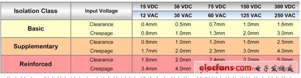
Figure 2: This table shows the isolation gap and creepage distance values ​​specified by the UL for the input voltage. The value of enhanced isolation is approximately three times higher than the basic isolation value.
High TG PCB - High Temerature Circuit Board for PCB applications that requires high temperature.
In recent years, there are more and more customers request to manufacture PCB with high Tg.
If you work with Printed Circuit Boards in your industry, you may or may not be familiar with the high-TG PCBs. Since the effective operation of your printed circuit boards is so important to your business, it may be in your best interest to understand a little bit more about high-TG printed circuit boards.
What Is High-TG Printed Circuit Board?
Tg means Glass Transition Temperature. As flammability of printed circuit board (PCB) is V-0 (UL 94-V0), so if the temperature exceeds designated Tg value, the board will changed from glassy state to rubbery state and then the function of PCB will be affected.
If working temperature of your product is higher than normal (130-140C), then have to use high Tg material which is > 170C. and popular PCB high value are 170C, 175C, and 180C. Normally the PCB Tg value should be at least 10-20C higher than working temperature of product. If you 130TG board, working temperature will be lower than 110C; if use 170 high TG board, then maximum working temperature should be lower than 150C.
When Do You Need a High-Temperature Circuit Board?
You need a high-temperature circuit board for your applications if your PCB will be experiencing a thermal load no greater than 25 degrees Celsius below the TG. If your product will be operating in the 130-degree Celsius range or higher, you will want to use a high-TG PCB to be safe. The main reason for the Hi TG PCB is because of the movement to RoHS pcb`s. It is causing most of the pcb industry to move toward Hi TG materials because of the higher temperatures needed for the lead-free solder to flow.
Applications for High-Temp PCBs
If you are working with high power density designs whose heat generation is likely to overwhelm your heat sinks or other heat management methods, a high-TG PCB is really the only answer. Trying to reduce the heat generation of your PCB may affect the weight, cost, power requirements or size of your application, and it is usually much more cost-effective and practical to simply start with a high-temperature heat-resistant PCB.
High temperatures can be disastrous for unprotected PCBs, damaging dielectrics and conductors, creating mechanical stresses due to differences in thermal expansion rates and ultimately causing everything from inconsistent performance to total failure. If your applications are in any danger of subjecting your PCBs to extreme temperatures or the PCB is required to be RoHS Compliant, it will be in your best interest to look into high-TG PCBs.
- Multilayer PCB boards with many layers
- Industrial electronics
- Automobile electronics
- Fineline trace structures
- High-temperature electronics
Considerations for Heat Dissipation
High-TG PCBs will be very important when you are looking to protect your printed circuit boards from the high temperatures of your application`s process or during the extreme temperatures of lead free assembly, but you will naturally want to consider multiple methods of drawing the extreme heat generated by electronic applications away from your board.
There are three considerations for dissipating the high heat generated by the action of electronics with printed circuit boards: convection, conduction and radiation.
Convection heat transfer is the process of transferring heat to air or water to allow it to flow away from an area - for example, when fluid absorbs heat and flows to a heat sink where it cools. Convection can also refer to the use of a fan or pump to force air over the surface, drawing heat away with it.
In most printed circuit boards, you will find a convection system where convection, usually including a cooling air fan, bears the heat through thermal vias to large, emissive heat sinks connected to conductive backings.
Conduction heat cools by putting the heat sink in direct contact with the heat source, allowing the heat to flow away from the source much like an electrical current flows through a system.
Designers dissipate radiation heat by making sure to design a direct path for electromagnetic waves to flow away from the source. Although electromagnetic wave radiation does not generate a tremendous amount of heat, if the board is designed to put reflective surfaces in the path of these waves, it can cause a rebound effect and significantly magnify the amount of heat that radiation generates on the board.
You can see that the more heat you need to deal with, the more it affects the design of the board. Reducing power density can limit the effectiveness of your product while adding heat sinks and fans can increase size, weight and cost. This is why, even if you are aware of other effective methods of heat management, it can be a very good idea to look into high-TG materials as part of your overall heat control solution.
High TG PCB Materials
At Bittele Electronics, we offer Complete PCB Assembly solutions for all types of High-Quality PCB Fabrication and High-Quality PCB Assembly requirements. Among the most common special requirements for PCB Fabrication is the need for high-temperature tolerance to withstand demanding operating conditions and/or environments.
We often encounter questions from our clients about the temperature requirements for the PCB Assembly Process itself, and whether or not a specific material selection will be required for Lead-Free PCB Assembly. Since our facilities are all fully RoHS Compliant, all of our default materials are suited to the higher Reflow Soldering temperatures of lead-free processes. You never have to worry about selecting a more robust heat profile for the production process itself, but in some cases, the finished boards must operate at high-temperature levels for prolonged periods. In this case, we provide a selection of PCB Materials that can meet your specific needs.
Temperature profiles for PCB material are generally expressed through the Tg (Glass Transition Temperature) of the material. This metric notes the temperature at which the stiff, glass-like polymer softens and is subject to warping or other physical defects. If you do not specify a minimum Tg level for your boards in your PCB Design Files, we will normally use our default Tg 140 FR4 material, which is sufficient to withstand the reflow soldering process and the majority of standard operating conditions.
We also offer higher Tg materials for your convenience, such as Tg 170 FR4 material, and IT180A with a characteristic Tg 180. We still offer all of our Standard PCB Options with high-Tg boards, so you will not have to worry about changing your design as a result of this material selection. The chart below shows a selection of PCB materials and their characteristics for your reference.
What Is FR-4?
FR-4 is a grade designation for flame-retardant fiberglass reinforced epoxy material. Thus, FR-4 PCB offers a much greater level of resistance to heat than a standard PCB. FR-4 circuit boards are divided into four classifications that are determined by the number of copper trace layers found in the material:
• Single-sided PCB / Single-layer PCB
• Double-sided PCB / Double-layer PCB
• Four or more than 10 layers PCB / Multilayer PCB
The characteristics of High Tg materials are listed below:
- Higher heat resistance
- Lower Z-axis CTE
- Excellent thermal stress resistance
- High thermal shock resistance
- Excellent PTH reliability
- Pcbway offers some popular High Tg materials
- S1000-2 & S1170: Shengyi materials
- IT-180A: ITEQ material
- TU768: TUC material
Technical options for High-Tg circuit boards
CTE-z
The CTE value shows the thermal expansion of the base material. CTE-z represents the z-axis and is e.g. due to the stability of the vias, of high importance. A higher Tg value favors a low CTE-z value which represents the absolute expansion in the z-axis. Errors like pad lifting, corner cracks and cracks within the via can be prevented through a low CTE-z value.

T260 - T288 value, Td
The decomposition temperature Td of a resin system depends on the binding energies within the polymers, and not on the glass transition temperature Tg. A good indicator for this characteristic is the T260 or T288 value, which specifies the time until delamination at 260°C or 288°C, respectively.
A very important indicator of the heat resistance is the time-to-delamination at a certain temperature. This test is preferably performed at 260 °C or 288 °C. The T260- or T288-value is the time to delamination of the tested material at 260 °C or 288 °C, repectively.
Td: Temperature-of-decomposition indicates the temperature at which the base material has lost 5% by weight and is an important parameter for the thermal stability of a base material. Through exceeding this temperature an irreversible degradation and damage to the material by the decomposition occurs.
High TG PCB Advantages
- High glass flow temperature value (TG)
- High-temperature durability
- Long delamination durability
- Low Z-axis expansion (CTE)
 |
") |
High TG PCB manufacturer and manufacturing capability
JHY PCB can manufacture High-Tg Circuit Boards with a Tg value of up to 180°C.
We used below High Tg materials usually, if you need Data Sheet, please contact us directly.
|
Material |
TG |
Td |
CTE-z |
Td260 |
Td288 |
|
(DSC, °C) |
(Wt, °C) |
(ppm/°C) |
(min) |
(min) |
|
|
S1141 (FR4) |
175 |
300 |
55 |
8 |
/ |
|
S1000-2M (FR4) |
180 |
345 |
45 |
60 |
20 |
|
IT180A |
180 |
345 |
45 |
60 |
20 |
|
Rogers 4350B |
280 |
390 |
50 |
/ |
|
High TG PCB
Blank PCB,High TG PCB,High TG Circuit Board,High TG Printed Circuit Board
JingHongYi PCB (HK) Co., Limited , https://www.pcbjhy.com