Ian Moulding - Automotive Marketing Manager, Diodes
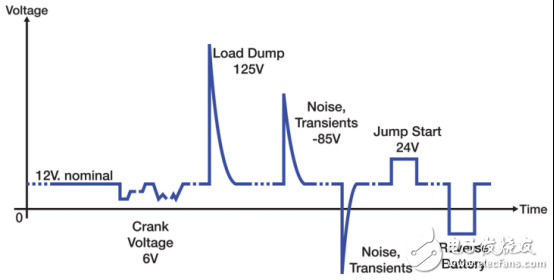
I’ve mentioned numerous times that the automotive electronics environment is incredibly stringent! As depicted in Figure 1, the car's rated battery voltage can fluctuate up to 125V DC at -12V DC (in a reverse battery condition) due to load transients and inductive field decay. Combine this with varying operating temperatures, interconnect issues, and open environments, and you're faced with a significant risk of ESD damage from human interaction. Clearly, your operating conditions are far more demanding than those in the consumer market.
The automotive sector demands cost-effective yet fully reliable solutions. However, this harsh environment presents a massive challenge to the power semiconductor devices needed for the multitude of control functions present in modern vehicles.
Traditional MOSFETs, while standard, often prove insufficiently robust for many automotive applications. Inductive surges and load dumps necessitate larger MOSFETs or external clamps to absorb transient energy that could otherwise destroy the MOSFET. Both alternatives add cost and complexity to individual designs.
Developed by Diodes and others, the self-protecting MOSFET addresses this issue with a monolithic topology that integrates clamping and other protective functionalities. This results in a more reliable, lower-cost, and smaller solution for driving relays, LEDs, and other inductive loads.
---
### Relay Drive
Diodes' DMN61D8LQ is a self-protecting MOSFET in an SOT23 package, specifically optimized for driving automotive relays while meeting cost and performance requirements. It features ESD protection in the input section and active clamping in the output section. The latter is particularly beneficial when switching relays, which are inherently inductive. Large transients are generated upon deactivating the relay, potentially damaging unprotected MOSFETs.
The back-to-back Zener stack (as shown in Figure 2), located between the gate and drain of the MOSFET, forms the core of this low-side, active clamp configuration. The clamp voltage is determined by the Zener stack voltage and is designed to be lower than the collapse voltage of the MOSFET’s drain-to-source junction while being high enough to avoid triggering during normal operation.
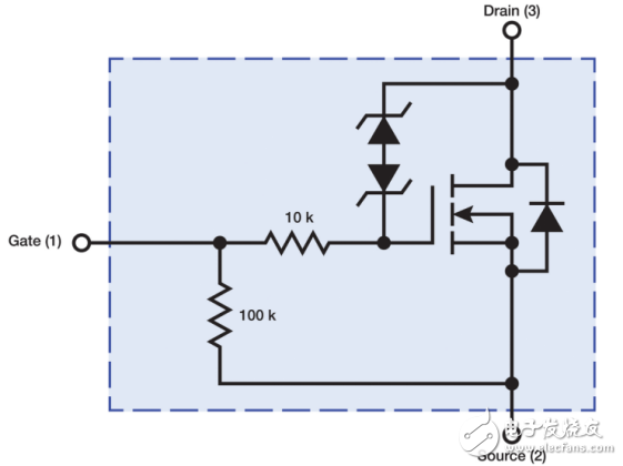
This ensures that when the MOSFET is turned off (with the input grounded), the voltage at the drain pin rises above the Zener stack voltage, allowing current to flow to ground via the Zener and input resistors. Once the final voltage generated at the MOSFET gate reaches the threshold, the MOSFET begins conducting and absorbs the load current.
By doing so, the inductive energy produced by deactivating the relay is absorbed by the power MOSFET operating in its normal active region, preventing excessive energy dissipation in the reverse collapse mode. Additionally, since the clamp voltage is lower than the sag voltage, the MOSFET consumes less power in clamp mode compared to sag mode, enhancing its energy-handling capability.
---
### Lamp Driver
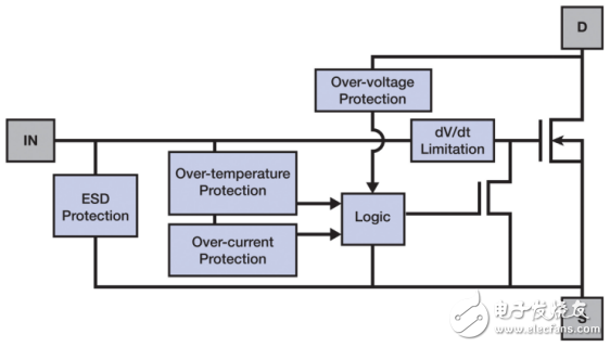
For even greater resilience against transients, self-protecting MOSFETs like Diodes' ZXMS6004FFQ employ a fully protected topology, including overtemperature and overcurrent protection circuitry. As illustrated in the block diagram of Figure 3, overvoltage and ESD input protection have been integrated. Available in a small SOT23 package, it’s six times smaller than the equivalent SOT223 package.
This MOSFET incorporates a temperature sensor and thermal shutdown circuitry to prevent overheating. The circuit activates when the MOSFET is on and triggers when the critical temperature (usually 175°C) is exceeded. The MOSFET then turns off and interrupts the current to limit further heat dissipation. Built-in hysteresis enables automatic recovery once the unit cools down by approximately 10°C.
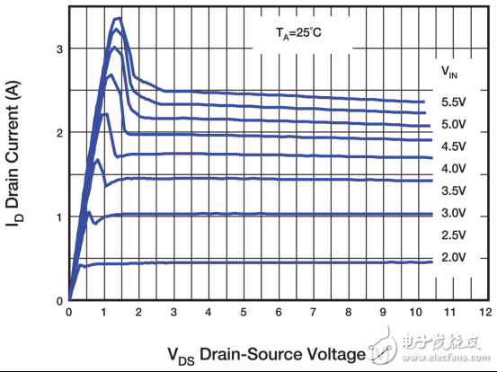
When turning off an incandescent lamp, the resistance is low. Upon turning on, resistance increases rapidly, causing a temperature rise. The overcurrent protection provided by the current-limiting circuit not only safeguards against faults but also prevents high surge currents linked to the low on-resistance of the luminaire. The current-limiting circuit detects a significant increase in the MOSFET source voltage (VDS) due to overload current and responds by reducing the internal gate drive and limiting the drain current (ID). This feature protects the MOSFET and prolongs the lifespan of the lamp. Its characteristics are shown in Figure 4.
Although these protection circuits operate independently, they can work together effectively. For instance, overcurrent regulation may function for a period without stopping the temperature from eventually reaching the threshold for entering a thermal runaway cycle.
With its integrated protection mechanisms, the self-protecting MOSFET offers a cost-effective solution for switching various automotive loads. Its internal features enhance system reliability, while the compact size of Diodes' SOT23 package reduces both space and cost compared to competing devices.
In conclusion, the automotive industry requires innovative solutions that balance cost efficiency with reliability. Self-protecting MOSFETs from companies like Diodes are paving the way for safer, more efficient vehicle electronics systems.
Engine drive Pump:
. Pump driven by diesel engine directly
. Pump driven by gas engine directly
. Water pump stantion
. Oil pump station
Engine Pump,Gas Engine Pump,Engine Driven Pump,Diesel Engine Pump
Guangdong Superwatt Power Equipment Co., Ltd , https://www.swtgenset.com