Many LCD modules use resistive touch screens. These touch screens are equivalent to sensors that convert physical locations to voltage values ​​that represent X and Y coordinates. There are usually 4-wire, 5-wire, 7-wire and 8-wire touch screens. This article describes in detail the structure of the SAR, the structure and implementation of the four touch screens, and the methods for detecting touch.
A resistive touch screen is a sensor that converts the physical location of a touch point (X, Y) in a rectangular area to a voltage representative of the X and Y coordinates. Many LCD modules use a resistive touch screen. This screen can use four-wire, five-wire, seven-wire, or eight-wire to generate the screen bias voltage and read back the voltage at the touch point.
In the past, in order to read the touch point coordinates on the resistive touch screen into the microcontroller, a dedicated touch screen controller chip was used, or a complex external switch network was used to connect the microcontroller's on-chip analog-to-digital converter (ADC). Sharp's LH75400/01/10/11 series and LH7A404 microcontrollers all have an on-chip ADC with a touch screen bias circuit that uses a successive approximation register (SAR) type converter. Using these controllers allows a direct interface between touch screen sensors and microcontrollers to control all touch screen bias voltages without CPU intervention and record all measurement results. This article will introduce in detail the structure and implementation principle of the four-wire, five-wire, seven-wire and eight-wire touch screens.
There are many ways to implement SAR SAR, but its basic structure is very simple. See Figure 1.
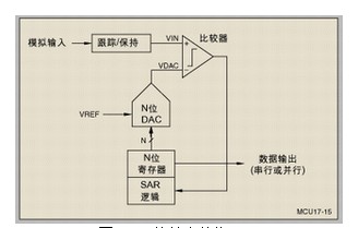
Fig. 1 The basic structure of the SAR This structure stores the analog input voltage (VIN) in a track/hold, and the N-bit register is set to the middle value (ie, 100.....0, where the highest bit is set to 1). Perform a binary lookup algorithm. Therefore, the output of the digital-to-analog converter (DAC) (VDAC) is one-half of VREF, where VREF is the reference voltage of the ADC. After that, perform a comparison operation again to determine if VIN is less than or greater than VDAC:
1. If VIN is less than VDAC, the comparator output logic is low and the highest bit of the N-bit register is cleared.
2. If VIN is greater than VDAC, the comparator output logic high (or 1) and the highest bit of the N-bit register remains at 1.
Thereafter, the control logic of the SAR moves to the next bit, forcing the bit to be high, and then performing the next comparison. The SAR control logic will repeat the above sequence of operations until the last bit. When the conversion is complete, an N-bit data word is available in the register.
Figure 2 shows an example of a 4-bit conversion process where the Y-axis and thick line represent the output voltage of the DAC.
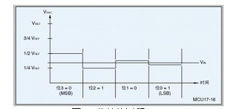
Figure 2 4-bit conversion process in this example:
1. The first comparison shows that VIN is less than VDAC, so bit [3] is set to zero. The DAC is then set to 0b0100 and the second comparison is performed.
2. In the second comparison, VIN is greater than VDAC, so bit [2] remains at 1. Subsequently, the DAC is set to 0b0110 and a third comparison is performed.
3. In the third comparison, bit [1] is set to 0. The DAC is then set to 0b0101 and the last comparison is performed.
4. In the last comparison, Bit[0] remains at 1 because VIN is greater than VDAC.
The touch screen principle The touch screen consists of two transparent layers stacked one above the other. The four-wire and eight-wire touch screens consist of two layers of transparent resistive materials with the same surface resistance. The five-wire and seven-wire touch screens consist of a resistive layer and a conductive layer. It is also common to use an elastic material to separate the two layers. When the pressure on the surface of the touch screen (such as pressing with a pen tip or a finger) is large enough, contact between the top layer and the bottom layer occurs. All resistive touch screens use the voltage divider principle to generate voltages that represent the X and Y coordinates. As shown in Figure 3, the voltage divider is implemented by connecting two resistors in series. The upper resistor (R1) is connected to the positive reference voltage (VREF) and the lower resistor (R2) is grounded. The voltage measurement at the two resistor connection points is proportional to the resistance of the next resistor.
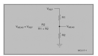
Figure 3 Voltage divider connected in series with two resistors To measure a coordinate in a specific direction on a resistive touch screen, a resistive layer needs to be biased: connect one side to VREF and the other to ground. At the same time, connect the unbiased layer to the high-impedance input of an ADC. When the pressure on the touch screen is large enough to make contact between the two layers, the resistive surface is divided into two resistors. Their resistance is proportional to the distance from the touch point to the offset edge. The resistance between the touch point and the ground is equivalent to the lower resistor in the voltage divider. Therefore, the voltage measured on the unbiased layer is proportional to the distance from the touch point to the ground.
The four-wire touchscreen four-wire touchscreen contains two resistive layers. One of them has a vertical bus at the left and right edges of the screen, and the other has a horizontal bus at the bottom and top of the screen. See Figure 4. To measure in the X-axis direction, the left side bus is biased to 0V and the right side bus is biased to VREF. Connect the top or bottom bus to the ADC and make a measurement when the top and bottom layers are in contact.
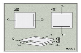
Figure 4 Two resistive layers of a four-wire touch screen To measure in the Y-axis direction, the top bus is biased to VREF and the bottom bus is biased to 0V. The ADC input is terminated to either the left bus or the right bus and the voltage can be measured when the top and bottom layers are in contact. Figure 5 shows a simplified model of a four-wire touch screen when two layers are in contact. For a four-wire touch screen, the ideal connection method is to connect the bus with the offset VREF to the positive reference input of the ADC and set the bus set to 0V to the negative reference input of the ADC.
The five-wire touch screen five-wire touch screen uses a resistive layer and a conductive layer. The conductive layer has a contact, usually on one side of its edge. Each of the four corners of the resistive layer has one contact. To measure in the X-axis direction, offset the upper left and lower left corners to VREF, and ground in the upper right and lower right corners. Since the left and right corners have the same voltage, the effect is similar to that of connecting the left and right buses, similar to the method used in a four-wire touch screen.
In order to measure in the Y-axis direction, the upper left and upper right corners are biased to VREF, and the lower left and right corners are biased to 0V. Since the upper and lower corners are the same voltage, the effect is similar to that of the bus connecting the top and bottom edges, similar to the method used in a four-wire touch screen. The advantage of this measurement algorithm is that it keeps the voltage in the upper left and lower right corners unchanged; however, if you use grid coordinates, the X and Y axes need to be reversed. For a five-wire touch screen, the best connection method is to connect the upper left corner (offset to VREF) to the ADC's positive reference input and the lower left corner (offset to 0V) to the ADC's negative reference input.
Seven-line touch screen The seven-line touch screen is implemented in the same way as a five-line touch screen except that it adds a line to each of the upper left and lower right corners. When performing a screen measurement, connect a line in the upper-left corner to VREF, and connect the other line to the positive reference of the SAR ADC. At the same time, a line in the lower right corner is connected to 0V and the other line is connected to the negative reference of the SAR ADC. The conductive layer is still used to measure the voltage across the voltage divider.
In addition to the eight-wire touch screen adding a line to each bus, the eight-wire touch screen is implemented in the same way as a four-wire touch screen. For the VREF bus, one line is used to connect VREF, and the other line is the positive reference input to the digital-to-analog converter of the SAR ADC. For the 0V bus, one line is used to connect 0V, and the other line is used as the negative reference input for the digital-to-analog converter of the SAR ADC. Any of the four wires on the unbiased layer can be used to measure the voltage across the voltage divider.
Detecting Touches All touch screens can detect if a touch has occurred by pulling up one of the layers with a weak pull-up resistor and pulling down the other with a strong pull-down resistor. If the measured voltage of the pull-up layer is greater than a certain logic threshold, there is no touch, and if not, there is a touch. The problem with this approach is that the touch screen is a huge capacitor, and in addition it may be necessary to increase the capacitance of the touch screen leads in order to filter out the noise introduced by the LCD. A weak pull-up resistor connected to a large capacitor will increase the rise time and may result in the detection of a false touch.
Four-wire and eight-wire touch screens can measure the contact resistance, RTOUCH in Figure 5. RTOUCH is approximately proportional to touch pressure. To measure touch pressure, you need to know the resistance of one or two layers in the touch screen. The formula in Figure 6 gives the calculation method. It should be noted that if the measured value of Z1 is close to or equal to 0 (when the touch point is close to the grounded X bus in the measurement process), some problems will occur in the calculation, and this problem can be effectively improved by adopting a weak pull-up method.
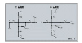
Figure 5 RTOUCH
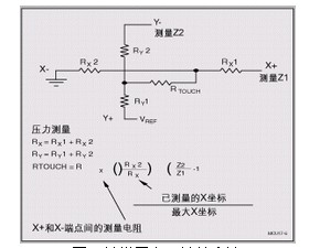
Figure 6 Touch Screen Resistance Calculation Method
A resistive touch screen is a sensor that converts the physical location of a touch point (X, Y) in a rectangular area to a voltage representative of the X and Y coordinates. Many LCD modules use a resistive touch screen. This screen can use four-wire, five-wire, seven-wire, or eight-wire to generate the screen bias voltage and read back the voltage at the touch point.
In the past, in order to read the touch point coordinates on the resistive touch screen into the microcontroller, a dedicated touch screen controller chip was used, or a complex external switch network was used to connect the microcontroller's on-chip analog-to-digital converter (ADC). Sharp's LH75400/01/10/11 series and LH7A404 microcontrollers all have an on-chip ADC with a touch screen bias circuit that uses a successive approximation register (SAR) type converter. Using these controllers allows a direct interface between touch screen sensors and microcontrollers to control all touch screen bias voltages without CPU intervention and record all measurement results. This article will introduce in detail the structure and implementation principle of the four-wire, five-wire, seven-wire and eight-wire touch screens.
There are many ways to implement SAR SAR, but its basic structure is very simple. See Figure 1.
Fig. 1 The basic structure of the SAR This structure stores the analog input voltage (VIN) in a track/hold, and the N-bit register is set to the middle value (ie, 100.....0, where the highest bit is set to 1). Perform a binary lookup algorithm. Therefore, the output of the digital-to-analog converter (DAC) (VDAC) is one-half of VREF, where VREF is the reference voltage of the ADC. After that, perform a comparison operation again to determine if VIN is less than or greater than VDAC:
1. If VIN is less than VDAC, the comparator output logic is low and the highest bit of the N-bit register is cleared.
2. If VIN is greater than VDAC, the comparator output logic high (or 1) and the highest bit of the N-bit register remains at 1.
Thereafter, the control logic of the SAR moves to the next bit, forcing the bit to be high, and then performing the next comparison. The SAR control logic will repeat the above sequence of operations until the last bit. When the conversion is complete, an N-bit data word is available in the register.
Figure 2 shows an example of a 4-bit conversion process where the Y-axis and thick line represent the output voltage of the DAC.
Figure 2 4-bit conversion process in this example:
1. The first comparison shows that VIN is less than VDAC, so bit [3] is set to zero. The DAC is then set to 0b0100 and the second comparison is performed.
2. In the second comparison, VIN is greater than VDAC, so bit [2] remains at 1. Subsequently, the DAC is set to 0b0110 and a third comparison is performed.
3. In the third comparison, bit [1] is set to 0. The DAC is then set to 0b0101 and the last comparison is performed.
4. In the last comparison, Bit[0] remains at 1 because VIN is greater than VDAC.
The touch screen principle The touch screen consists of two transparent layers stacked one above the other. The four-wire and eight-wire touch screens consist of two layers of transparent resistive materials with the same surface resistance. The five-wire and seven-wire touch screens consist of a resistive layer and a conductive layer. It is also common to use an elastic material to separate the two layers. When the pressure on the surface of the touch screen (such as pressing with a pen tip or a finger) is large enough, contact between the top layer and the bottom layer occurs. All resistive touch screens use the voltage divider principle to generate voltages that represent the X and Y coordinates. As shown in Figure 3, the voltage divider is implemented by connecting two resistors in series. The upper resistor (R1) is connected to the positive reference voltage (VREF) and the lower resistor (R2) is grounded. The voltage measurement at the two resistor connection points is proportional to the resistance of the next resistor.
Figure 3 Voltage divider connected in series with two resistors To measure a coordinate in a specific direction on a resistive touch screen, a resistive layer needs to be biased: connect one side to VREF and the other to ground. At the same time, connect the unbiased layer to the high-impedance input of an ADC. When the pressure on the touch screen is large enough to make contact between the two layers, the resistive surface is divided into two resistors. Their resistance is proportional to the distance from the touch point to the offset edge. The resistance between the touch point and the ground is equivalent to the lower resistor in the voltage divider. Therefore, the voltage measured on the unbiased layer is proportional to the distance from the touch point to the ground.
The four-wire touchscreen four-wire touchscreen contains two resistive layers. One of them has a vertical bus at the left and right edges of the screen, and the other has a horizontal bus at the bottom and top of the screen. See Figure 4. To measure in the X-axis direction, the left side bus is biased to 0V and the right side bus is biased to VREF. Connect the top or bottom bus to the ADC and make a measurement when the top and bottom layers are in contact.
Figure 4 Two resistive layers of a four-wire touch screen To measure in the Y-axis direction, the top bus is biased to VREF and the bottom bus is biased to 0V. The ADC input is terminated to either the left bus or the right bus and the voltage can be measured when the top and bottom layers are in contact. Figure 5 shows a simplified model of a four-wire touch screen when two layers are in contact. For a four-wire touch screen, the ideal connection method is to connect the bus with the offset VREF to the positive reference input of the ADC and set the bus set to 0V to the negative reference input of the ADC.
The five-wire touch screen five-wire touch screen uses a resistive layer and a conductive layer. The conductive layer has a contact, usually on one side of its edge. Each of the four corners of the resistive layer has one contact. To measure in the X-axis direction, offset the upper left and lower left corners to VREF, and ground in the upper right and lower right corners. Since the left and right corners have the same voltage, the effect is similar to that of connecting the left and right buses, similar to the method used in a four-wire touch screen.
In order to measure in the Y-axis direction, the upper left and upper right corners are biased to VREF, and the lower left and right corners are biased to 0V. Since the upper and lower corners are the same voltage, the effect is similar to that of the bus connecting the top and bottom edges, similar to the method used in a four-wire touch screen. The advantage of this measurement algorithm is that it keeps the voltage in the upper left and lower right corners unchanged; however, if you use grid coordinates, the X and Y axes need to be reversed. For a five-wire touch screen, the best connection method is to connect the upper left corner (offset to VREF) to the ADC's positive reference input and the lower left corner (offset to 0V) to the ADC's negative reference input.
Seven-line touch screen The seven-line touch screen is implemented in the same way as a five-line touch screen except that it adds a line to each of the upper left and lower right corners. When performing a screen measurement, connect a line in the upper-left corner to VREF, and connect the other line to the positive reference of the SAR ADC. At the same time, a line in the lower right corner is connected to 0V and the other line is connected to the negative reference of the SAR ADC. The conductive layer is still used to measure the voltage across the voltage divider.
In addition to the eight-wire touch screen adding a line to each bus, the eight-wire touch screen is implemented in the same way as a four-wire touch screen. For the VREF bus, one line is used to connect VREF, and the other line is the positive reference input to the digital-to-analog converter of the SAR ADC. For the 0V bus, one line is used to connect 0V, and the other line is used as the negative reference input for the digital-to-analog converter of the SAR ADC. Any of the four wires on the unbiased layer can be used to measure the voltage across the voltage divider.
Detecting Touches All touch screens can detect if a touch has occurred by pulling up one of the layers with a weak pull-up resistor and pulling down the other with a strong pull-down resistor. If the measured voltage of the pull-up layer is greater than a certain logic threshold, there is no touch, and if not, there is a touch. The problem with this approach is that the touch screen is a huge capacitor, and in addition it may be necessary to increase the capacitance of the touch screen leads in order to filter out the noise introduced by the LCD. A weak pull-up resistor connected to a large capacitor will increase the rise time and may result in the detection of a false touch.
Four-wire and eight-wire touch screens can measure the contact resistance, RTOUCH in Figure 5. RTOUCH is approximately proportional to touch pressure. To measure touch pressure, you need to know the resistance of one or two layers in the touch screen. The formula in Figure 6 gives the calculation method. It should be noted that if the measured value of Z1 is close to or equal to 0 (when the touch point is close to the grounded X bus in the measurement process), some problems will occur in the calculation, and this problem can be effectively improved by adopting a weak pull-up method.
Figure 5 RTOUCH
Figure 6 Touch Screen Resistance Calculation Method
Mono panel,High Quality Mono panel,Mono panel Details, Yangzhou Bright Solar Solutions Co., Ltd.
Yangzhou Bright Solar Solutions Co., Ltd. , https://www.solarlights.pl