The MICRF009 is a single-chip SK/OOK (on-off key) RF receiver IC developed by Micrel Semiconductor. It offers enhanced performance in two critical areas: improved sensitivity, reaching up to 104dBm, and faster recovery times, typically as quick as 1ms. Like other QwikRadio products, the MICRF009 is designed for low power consumption and high integration, making it ideal for a wide range of wireless applications.
One of the key features of the MICRF009 is its dual operation modes: fixed mode (FIX) and scan mode (SWP). In FIX mode, the device functions as a traditional superheterodyne receiver, offering superior selectivity and sensitivity. In SWP mode, it can scan a broader RF spectrum using a patented scanning function, allowing it to work with less accurate, low-cost transmitters. This flexibility makes the MICRF009 suitable for both precise and variable frequency applications.
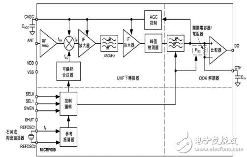
Figure 1. Block diagram of MICRF009
The MICRF009 integrates all post-detection (demodulator) data filtering, eliminating the need for an external baseband filter. Users can choose between two filter bandwidths depending on the data rate and modulation format. The IC operates within the 300MHz to 440MHz frequency range and supports data rates up to 2Kbps in fixed mode using Manchester encoding. Its low RF repeating radiation ensures efficient and reliable communication.
As shown in Figure 1, the MICRF009 consists of three main components: a UHF down converter, an OOK demodulator, and a reference clock and control logic. It also includes internal capacitors (CTH, CAGC) and a timing component such as a quartz crystal or ceramic resonator. Along with power coupling capacitors and an antenna impedance matching network, these are the only external components needed to build a complete UHF receiver using the MICRF009. For optimal performance, the device should be properly impedance matched to the antenna, requiring just a few additional components.
Designing a complete UHF receiver with the MICRF009 involves five essential steps: selecting the operating mode, choosing the reference oscillator, setting the demodulator filter bandwidth, selecting the CTH capacitor, and choosing the CAGC capacitor.
1. Selecting the Operating Mode
(1) Fixed Mode
When the transmitter frequency is precisely set—such as when using SAW or quartz crystal components—the MICRF009 can be configured as a standard superheterodyne receiver. In this mode, the narrow RF bandwidth provides strong immunity to interfering signals. To activate fixed mode, connect the SWEN pin to ground.
(2) Scan Mode
When used with a low-cost LC transmitter, the MICRF009 should be configured in scan mode. In this mode, the local oscillator (LO) sweeps through a band wider than the data rate, effectively increasing the RF bandwidth. This allows the device to handle significant frequency offsets between the transmitter and receiver. Even if the transmitter frequency drifts up to ±0.5%, the receiver remains functional without adjustment. The IF bandwidth remains at 680kHz, ensuring consistent noise performance. However, the maximum data rate in scan mode is limited to approximately 1250 Hz.
2. Selecting the Reference Oscillator
The MICRF009 uses an internal Colpitts reference oscillator for timing and tuning, controlled via the REFOSC pin. The oscillator can be connected to a ceramic resonator, a quartz crystal, or an external signal. The required reference frequency depends on the transmit frequency and the selected operating mode.
(1) Quartz Crystal or Ceramic Resonator Selection
If using a quartz crystal, ensure it has low ESR and avoid those with built-in capacitors. For fixed mode, a crystal is recommended, while in scan mode, either a crystal or ceramic resonator can be used. The minimum input voltage should be 300mVPP for crystals and ceramic resonators, and 0.1VPP to 1.5VPP for external signals.
(2) Calculating the Reference Oscillator Frequency fT
In fixed mode, the local oscillator frequency fLO is calculated using fLO = fTX ± 0.86(fTX / 315), and fT is derived from fLO using fT = 2 × fLO / 64.5. In scan mode, fT is given by fT = 2 × fTX / 64.25. The precision required for the reference oscillator is lower in scan mode, but for very inaccurate transmitters, a crystal is still recommended.
3. Selecting the CTH Capacitor
The CTH capacitor works with the internal RSC resistor to compress the DC level of the demodulated signal. The time constant τ should be around five times the data rate. At 315MHz, RSC is 145kΩ, and this value scales inversely with frequency. The CTH capacitance is calculated as CTH = τ / RSC. A ±20% X7R ceramic capacitor is usually sufficient.
4. Selecting the CAGC Capacitor
The CAGC capacitor sets the AGC response time, which is crucial for maximizing system range. A capacitance of at least 0.47μF is recommended to minimize ripple in the AGC control voltage. In duty cycle mode, the capacitor must have low leakage to maintain voltage during power-down periods. After reactivation, the AGC capacitor needs to be replenished quickly, and the pull-up/pull-down current ratio is 45:1.
5. Selecting the Demodulator Filter Bandwidth
The SEL0 pin controls the demodulator filter bandwidth in binary steps. In scan mode, it ranges from 625Hz to 1250Hz, while in fixed mode, it ranges from 1250Hz to 2500Hz. The exact values depend on the operating frequency, and Table 3 shows the relationship between SEL0 and the filter bandwidth.
Additional considerations include power supply bypass capacitors, optimizing the bandpass filter for better selectivity, and reducing output noise through analog or digital suppression techniques. The CTH pin can be biased with a resistor to suppress noise, and typical values range from 10M to 6.8M ohms.
The I/O pins require appropriate interface circuits, and the antenna impedance must be matched to the IC’s input for optimal performance. A simple L-shaped matching network can achieve 50Ω impedance, and the inductor values depend on the PCB material and layout.
An example application of the MICRF009 in scan mode at 315MHz is shown in Figure 8, with a BOM listed in Table 5 and a corresponding PCB layout in Figure 9. This design demonstrates the versatility and ease of use of the MICRF009 in real-world UHF communication systems.
LED Par can
LED PAR LIGHT Series
54X3W rgbw; 18x12w RGBW;24x12w RGBW is hot selling in the market. It have waterproof and non-waterproof
Features:
- RGBWA+UV color, 6-in-1 LEDs, excellent color mixing
- quiet working, suitable for quiet applications like theater, studio,etc
-
suitable for events where indoor/outdoor flexibility is needed
- Adjustable PWM (Pulse Width Modulation) to avoid flickering on camera
- Advanced optics provide exceptional color mixing and high efficiency
- Smooth dimming curves for eliminate flicker and choppiness in fades
Our company have 13 years experience of LED Display and Stage Lights , our company mainly produce Indoor Rental LED Display, Outdoor Rental LED Display, Transparent LED Display,Indoor Fixed Indoor LED Display, Outdoor Fixed LED Display, Poster LED Display , Dance Led Display... In additional, we also produce stage lights, such as beam lights Series, moving head lights Series, LED Par Light Series and son on...
LED Par Light Series,Led Par Can Lights,Par Can,Led Par Stage Light
Guangzhou Chengwen Photoelectric Technology co.,ltd , https://www.cwleddisplay.com