With the rapid development of computers and information technology, DSPs with fast and high-precision processing capabilities have emerged and are widely used. This paper designs a system that realizes the control of the motion camera through the DSP, which can make the shooting work that cannot be performed in the conventional way easy and achieve the desired effect. The camera quickly reaches the specified position, takes 5 shots, and ensures that the captured image is not distorted.
1 System principle
A DSP-based motion camera control system block diagram is shown in Figure 1.
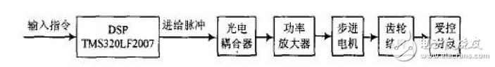
Figure 1 DSP-based motion camera control system block diagram
The DSP processes the input commands under the driving of the GPIO. After photoelectric coupling and power amplification, the stepper motor is driven to work, and the stepping motor and the gear structure on the camera frame are connected to control the camera to complete the 5-point shooting work.
The control principle of the motion camera is shown in Figure 2. The motion camera control system needs to complete the camera to quickly move to a specified position at a certain moment, stop immediately, aim at the target and ensure the image is clear, then use the same standard at 2 o'clock, 3 o'clock, 4 o'clock, 5 o'clock. Take a photo, then press the original way to quickly return to the position 1 point, waiting for the next shooting cycle.

Figure 2 Motion camera control principle
2 system hardware design
In the motion camera control system, it is necessary to control the camera to perform a "repetitive start and stop" motion, that is, to require the camera to move quickly at certain moments, to stop quickly at a specific moment, and to ensure that the camera is stationary when stopped, and to ensure that the captured image is not distortion. Therefore, the selected motor should be easy to start and stop control, but also has the ability to lock. This system uses a stepping motor widely used in motion control systems as an actuator.
The stepping motor is designed according to the theory of the combined electromagnet, and is an open-loop control element that converts the effective electric pulse signal into a corresponding angular displacement or linear displacement. The stepping motor supplies the electric pulse signal to the control windings of each phase of the stator through a dedicated power supply, and generates a pulse magnetic field similar to the rotating magnetic field in the air gap, so that each stepping motor adds a pulse signal, and the stepping motor moves. step. The speed and stop position of the stepping motor depend only on the frequency of the input pulse signal and the number of pulses. It does not require feedback information and A/D conversion, and can directly convert the digital pulse signal into a controllable angular displacement. Stepper motors are only suitable for motion camera control systems because they have periodic errors without cumulative errors, smooth speed regulation over a wide range, self-locking capability, and easy start-stop control. The control system of the stepper motor is shown in Figure 3. When the stepper motor and load have been determined, the performance of the entire drive system is completely dependent on the drive power and control method. The stepper motor driver consists of pulse signal, signal distribution, and power amplifier. The pulse distribution method adopts software pulse distribution, and the software uses pulse distribution without changing the hardware circuit. Only the software program can be modified to complete the control scheme modification, which not only reduces the cost but also improves the reliability.

Figure 3 Stepper motor control system block diagram
According to the dynamic requirements of the load camera of the motor, the relationship between the motor movement law and the camera exposure time during the camera sweep, the ASM46AK-H100 harmonic deceleration stepper motor is selected. The ASM46AK-H100 stepper motor has a reduction ratio of 1:100, the highest resolution is set to 0.36(°)/pulse, the torque is 5 N·m, the maximum torque is 11 N·m, and the power input current is 1.7 A. The power input voltage is DC 24 V, the maximum input pulse frequency is 250 kHz (pulse duty ratio is 50), and the speed/position control command is pulse sequence input. The allowable speed range is 0 to 24 r/min, which can meet the requirements of CCD. When the overload protection, overvoltage protection, speed difference abnormal protection, speed is too fast, EPROM data error, sensor abnormality, system abnormality and other protection functions work, the alarm signal is output and the motor stops naturally.
The stepper motor driver selects the matching ASD18A-K driver. The ASD18A-K driver provides control power, speed control pulse, motion direction control pulse, phase A pulse output, phase B pulse output, timing, alarm, resolution conversion and current switching. And other electrical interfaces. The ASD18A-K driver can adjust the resolution, pulse input mode, current magnitude, and speed by the function switch. Reasonable selection of parameters can suppress the vibration during low-speed operation and make the action at startup more stable.
DSP selects the cost-effective and excellent digital signal processor TMS320LF2407, which integrates on-chip peripherals such as A/D, PWM generator, photoelectric encoder and interface circuit. Rich on-chip resources, 544 BDARAM, 2 KB SARAM, 32 KB FLASH, 2 event managers (each containing 2 16-bit general-purpose timers, 8 PWM channels, 3 capture units) for generating drivers PWM waveform of the motor, 16-channel 10-bit, ADC module with 500 ns conversion time for analog control A/D conversion, rich external memory interface (192K & TImes; 16 b: 64 KB program memory, 64 KB data memory) 64 KB I/O realizes isolation and voltage conversion between DSP and keyboard and liquid crystal display optocoupler), watchdog module, CAN, SCI, multiple GPIO, 5 external interrupts, PLL, etc. Very high computing performance, up to 40 MIPS, 25 ns instruction cycle. With rich development resources, JTAG, CCS, complete technical documentation support, 144 pin LQFP package. The I/O output of the TMS320LF2407 is a 3.3 V CMOS level. The 245 buffer is converted to a TTL level and the stepper motor driver ASD18A-K is driven. The ASD18A-K performs subdivision, ring distribution and power drive.
3 system software design
The control system program consists of a main program, a subroutine and an interrupt subroutine. The main program completes the system initialization and initialization of each variable. The subroutine completes the scanning of each control panel, and interrupts the subroutine to realize the function of setting various parameters on the control panel. The camera control flow chart is shown in Figure 4.
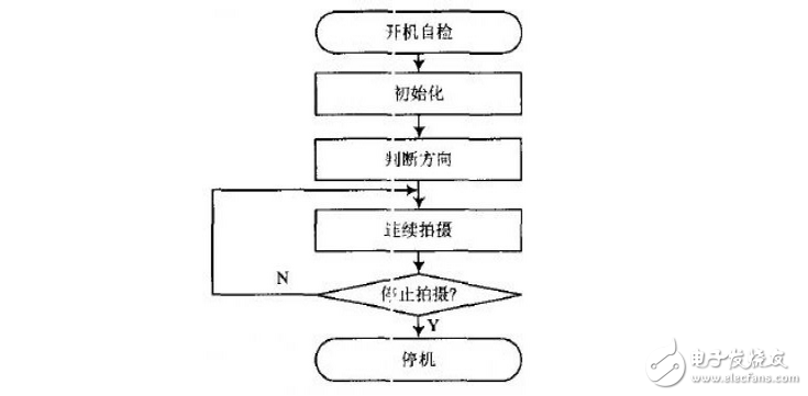
Figure 4 camera control flow chart
Since the TMS320LF2407 is connected to the driver through the I/O port, the interface initialization definition is required, IOPC5 is configured as the basic function mode; PWM3 IOPB2, IOPB5 is configured as the general-purpose I/O mode; IOPC5 is configured as the general-purpose I/O mode; In the motor driver design, the event management module of the TMS320LF2407 controller is fully utilized. There is a 16-bit compare register CMPRx (x=4, 5, 6) in each TMS32OLF2407. Each compare register has two compare PWM output pins, which generate three PWM output signals to control the motor speed (position). The polarity of the output pin will be determined by the control bit of the control register (ACTR). Select high or low as the turn-on signal as needed. In the PWM post-modulation, a certain carrier is required for the period. In this case, the timer 3 is used. It uses the internal CPU clock as the input and operates in the continuous up/down counting mode to generate the PWM pulse output. The generated pulse is a ring. Variable pulse, when an interrupt occurs during the underflow and overflow of the T3PR timing cycle, the cycle value is refreshed and PWM adjustment is performed.
4 Conclusion
This paper uses the digital signal processor TMS320LF2407 to drive the stepper motor driver ASD18A-K, and the embedded DSP control program to drive the ASM46AK-H100 harmonic deceleration stepper motor to achieve control of the motion camera, through laboratory simulation experiments, on-site The actual operation and data testing, the design of the control system meets the expected requirements.
Circular Connectors are mostly designed for commercial signal and power applications.Common classification is material: all plastic connector and metal connector, collectively known as CPC connector.Generally, stable high temperature resistant thermoplastic materials are used, and the working temperature is - 40 ℃ - 105 ℃.Fast connection / disconnection with the help of thread, with active braking coupling function.Built in male and female pin protection device.
Circular Connectors
Circular Connector,Circular Connector Types,Circular Power Connector,Circular Electrical Connectors
Suzhou WeBest Electronics Technology Co.Ltd , https://www.webestet.com