The commonality between all DACs is the definition and description of the technical specifications. This article will discuss static DAC specifications. The static DAC specification includes a description of the characteristics of the DAC in the DC domain. The digital and analog timing phenomena of the DAC are not part of this set of specifications when in the DC domain.
figure 1
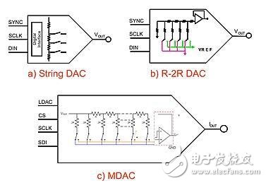
Although the three DAC topologies are different from each other, their specifications are very similar to the electrical description.
A major static DAC specification is the ideal transfer function (Figure 2). The definition of zero code, offset, full scale, and gain can be easily understood and understood in the diagram of this normal conversion function. Once you understand the above concepts, differential nonlinearity (DNL), integral nonlinearity (INL), and monotonic specifications become another derivative of the ideal transfer function.
figure 2
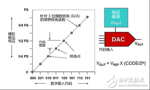
Ideal DAC conversion function
Figure 2 shows how a DAC can generate a single analog output value for a discrete value of a digital input code. The order of the numeric input codes in the figure is unipolar, where the code is added in a standard binary manner.
The analog range of the DAC conversion function in Figure 2 is from zero to the analog output full-scale (FS) value. The DAC voltage reference (VREF) establishes the least significant bit (LSB) or code width of the converter and sets the full-scale range (FSR). The size of the LSB is equal to VREF / 2N.
In Figure 2, "N" is equal to the resolution of the converter, and 2N is equal to the number of single bits of the converter. The number of codes the DAC has is equal to 2N. For a 3-bit converter, the number of codes is equal to 23 or 8. The conversion equation for this ideal transfer function is VOUT = VREF x (CODE/2N) and the full-scale output voltage is equal to VREF – 1LSB.
Zero code error
In Figure 3, the zero code error of the DAC is the most understandable static specification. We assume that this value is for a single-pole, single-supply DAC with a fully ideal minimum output voltage of 0 volts. When a digital value of 0 is loaded into the DAC register, a zero-scale error appears on the analog output pin of the DAC. This error is caused by the output swing performance of the internal output amplifier. For single-supply DACs, the zero-scale error is always positive, and the specification is in millivolts or microvolts.
image 3
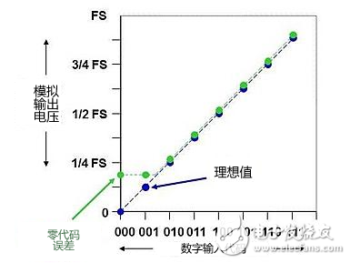
The zero-error operating state of the DAC's internal output amplifier due to the inability to reach the negative supply rail.
Offset error
However, the offset error is different. The offset error is present over most of the entire DAC conversion curve. In Figure 4, the simulated offset error varies over each code of the ideal conversion curve. As you can see from the figure, the conversion curve with offset error is the same as the ideal curve in the vertical direction along the x-axis. The unit of this specification is usually millivolts.
Figure 4
The offset error can be positive or negative, but it always affects each code with the same error.
Gain error
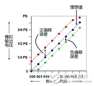
The concept of gain error is somewhat difficult to understand. In general, the gain error describes the change in the slope of the ideal DAC curve. Figure 5 illustrates this concept. The gain error specification is usually expressed as a percentage of the FSR and is calculated after the offset error is eliminated.
Figure 5

The gain error of the DAC causes the ideal transfer function to rotate around the zero crossing
Differential nonlinearity
Differential nonlinearity (INL) is a static specification, sometimes referred to as differential linearity. DNL is the maximum deviation of the actual analog output step size from the ideal step size of 1 LSB. This is evaluated on the entire actual transfer function curve (Figure 6). Since each code may need to be adjusted, it is difficult to calibrate this DAC error.
Figure 6
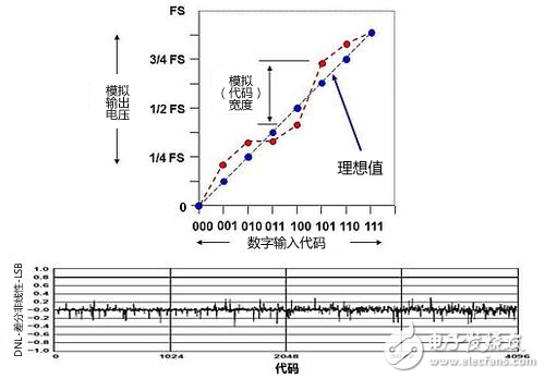
DNL represents the difference between each actual voltage output and the ideal curve. A 12-bit DAC DNL error curve where the x-axis is equal to the DAC code (0 to 4095) and the y-axis is equal to DNL.
For example, a DAC that has a 1.5 LSB output change for a 1 LSB digital code change exhibits a differential nonlinearity of 0.5 LSB. A DNL greater than 1 may indicate a missing code. The unit of measurement for differential nonlinearity is the fractional or percentage of full scale. Errors generated by DACs with DNL problems can affect gain control applications.
Monotonic
As a musician, I never understand the source of this term. In the field of music, the monotonous definition is that there is only one tone. But then we have to look at the definition of this DAC specification from another angle.
A differential nonlinearity of less than -1 LSB produces a non-monotonic transfer function for the DAC (Figure 7). If the DAC is non-monotonic, the amplitude of the DAC analog output is less than the increase in the digital input code and vice versa.
Figure 7
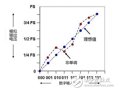
The non-monotonic DAC operating state is inverted in the analog-to-digital conversion relationship.
Any non-monotonic operating state exhibited by a DAC cannot determine if it will affect the system. For example, in an audio application, the listener can hear a brief, small analog output voltage and cannot detect a large input code. In other applications, this can be a significant problem that can cause system oscillations. For example, in a DC motor control system, the reduction in analog output voltage relative to the increase in input code may be easily misinterpreted as the system will perform the correction by reducing the input code.
Integral nonlinearity
Another DAC static specification is Integral Nonlinearity (INL), which is a measure of the slight deviation of the DAC's true transfer function from the ideal transfer function (Figure 8). Integral nonlinearity, linearity error, or INL is the highest value of the DNL error. This specification uses the optimal straight line or end-to-end (end point linear) line to quantify the INL in LSB.
Figure 8

The INL specification defines the worst case distance between the optimal straight line or end-to-end line and the ideal DAC conversion function.
Applications such as arbitration waveform generators require better INL.
Compare technical specifications between data sheets
When comparing one data table to another, the technical specifications may have different units of measure. For example, in one data table, the unit of offset error may be volts, while in another data table, the unit may be a percentage of LSB or FSR. Table 1 provides a calculation method for conversion between LSB, volts, FSR percentage, and PPM (parts per million).
Table 1
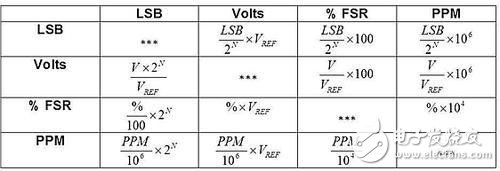
Technical specification unit conversion
in conclusion
The offset, gain, INL, and DNL operating states of the DAC can affect the overall system's effectiveness in a number of ways. However, there are many other influencing factors. In Part 4 of this DAC series, we will cover the definition of dynamic specifications such as settling time, glitch pulses and noise.
references
· "Make your DAC more accurate," Baker, Bonnie, EDN, October 26, 2006
· "Shrinking the Gap: DAC Application Tutorial (SNAA129)," McCulley, Bill, Texas Instruments (TI)
· “Shrinking the gap (Part 3): A review of the DAC application,†McCulley, Bill, EETImes Europe, July 6, 2010
Laminated Wood Screw And Nuts Insulation fasteners used in transformers, which is used in construction as insulation.
Phenolic Cotton Cloth Rod,Phenolic Cotton Cloth Nuts,Laminated Wood Screw And Nuts,Phenolic Cotton Cloth Rod And Nuts
Yingkou Dongyuan Electrical Insulation Board Co.,Ltd , https://www.dy-insulation.com