In today's cars, the ever-increasing electrical load poses a huge challenge to the battery. More than half of the car failures caused by the power system can be traced back to lead-acid batteries, which can be avoided if the battery status is known. In addition, new features in micro-hybrid vehicles such as start-stop or smart alternator control also require an accurate understanding of battery status.
The Battery Management System (BMS) provides the necessary information by quickly and reliably monitoring the state of charge (SoC), health status (SoH), and functional status (SoF) in the startup capability. As a result, BMS minimizes the number of car failures due to unexpected battery failures, resulting in maximum battery life and maximum battery efficiency, and can support CO2 reduction. The main component of the BMS is the Intelligent Battery Sensor (IBS), which measures the battery terminal voltage, current and temperature and calculates the state of the battery.
This article describes how to implement a BMS that uses the most advanced algorithms to calculate SoCs, SoHs, and SoFs, and how to efficiently implement these functions in Freescale's lead-acid battery IBS.
1 Introduction
In the past, the level of charge of a car battery has been an incomprehensible factor that can cause a car breakdown in many cases. Depending on the life of the car, the battery-related failure rate may climb to 10,000 ppm [1].
Another serious challenge that has existed for automotive batteries comes from the growing demand for electricity and power, as well as the need to reduce carbon dioxide emissions.
Because electronic systems play a very important role in the field of automotive innovation, the demand for power supply is increasing as cars develop in terms of comfort functions, safety-related functions, hybrid vehicles, driver assistance and infotainment. The higher it is.
On the other hand, more and more regulations have been issued to call for reductions in carbon dioxide emissions and fuel consumption.
In order to meet the above restrictions, an advanced power management system is required to ensure that the battery provides sufficient power for engine start-up in various work scenarios.
2) Power Management System
Typically, a typical power supply network used to support a start-stop system includes a body control module (BCM), a battery management system (BMS), a generator, and a DC/DC converter (see Figure 1).
The BMS provides battery status information to the BCM through dedicated load management algorithms to stabilize and manage the power supply network by controlling the generator and DC/DC converter. The DC/DC converter supplies power to various electrical components inside the car.
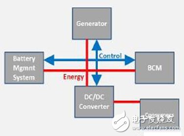
Figure 1: Example of a power supply network used in a typical start-stop system
Generator: Generator; Battery mgmnt system: Battery Management System; Energy: Power; Control: Control; AC/DC Converter: AC/DC Converter; Consumers: Electrical Components
Typically, the BMS of a lead acid battery is mounted directly into the smart connector of the battery clip. The connector includes a low-resistance shunt resistor (typically in the 100uOhm range) and a small PCB with highly integrated devices with accurate measurement and processing functions called smart battery sensors (IBS, see Figure 2) ). IBS measures battery voltage, current and temperature with high resolution and accuracy even under the toughest conditions, and accurately predicts battery state of charge (SoC) and health (SoH) throughout the life of the battery. And functional status (SoF). These parameters are transmitted to the BCM on a regular or on-demand basis via an automotive-certified in-vehicle network.

Figure 2: Typical smart battery sensor for lead-acid batteries
Battery Plus Pole: Battery Positive; Battery Minus Pole: Battery Negative; Chassis ground: Chassis ground; Precision measurement battery current, voltage & temperature: Accurately measure battery current, voltage and temperature; DeterminaTIon of key battery characterisTIcs: state of health (soh) State of charge (soc) state of funcTIon (sof): Determines the main battery characteristics: health status (SoH), state of charge (SoC), and functional status (SoF); CommunicaTIon to bcm: communicates with BCM
In addition to the above functional and parametric functions, other major requirements for IBS include low power consumption, in-vehicle communication interface conformance testing that can operate in harsh automotive environments (ie, EMC and ESD), and automotive OEM acceptance (ie, , LIN), to meet the automotive grade test limits (for the Six Sigma limit of the measured parameters), in addition to comply with the AEC-Q100 standard requirements.
Freescale has announced a fully integrated LIN battery monitoring device based on Freescale S12 MCU technology [2] that meets all of the above parameters. The device consists of three independent measurement channels: the current is measured by an external shunt resistor; the battery voltage is measured by a series resistor directly mounted on the negative pole of the battery; the temperature is measured by an integrated sensor. The sensor is directly connected to the LIN bus using an integrated LIN 2.1 interface, eliminating the need for additional components. Freescale IBS is fully compliant with the automotive industry's AEC-Q100 standard.
In the following chapters, we will introduce you to the implementation of BMS using Freescale IBS and how to achieve efficient operation of BMS by using the hardware features and fixed-point algorithms of IBS.
3) Battery monitoring
As mentioned in Section 2), the primary use of IBS is to monitor battery status and transfer state variables to BCM or other ECUs as needed. The battery monitor input value will use the measured battery current, battery voltage, and temperature sample values. Battery monitor output values ​​are SoC, SoH, and SoF values.
3.1) State of charge
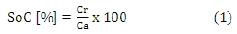
(SoC) The definition of SoC is very straightforward and is usually expressed as a percentage. The fully charged battery SoC is 100% and the fully discharged battery SoC is 0%. The SoC value changes as the battery is charged and discharged.
This value is calculated by equation (1), where Cr represents the remaining (dischargeable) charge of the battery and Ca represents the total available charge of the battery:
However, one problem is that the available battery power is often different from the nominal capacity of the battery (usually labeled on the label of the battery casing). For a new battery, it may be slightly higher than the nominal capacity, and for a battery that has been used for a while, the available power will decrease. Another problem is that the actual available power is difficult to determine based on the input value of the IBS.
Therefore, the SoC is usually rated at the nominal capacity Cn, which has several advantages:
• The total available charge of the battery of a particular SoC is known, including the old battery.
◠Test current at Cn point (I=Cn/20h) and temperature (27°C) are determinable
The coulomb counting algorithm is the best algorithm for tracking rapid changes in SoCs. It is based on the integration of current into and out of the battery and the adoption of a calculated SoC based on actual conditions. Equation (2) is used for SoC calculation, where Q(t0) represents the initial charge of the battery, α represents the performance factor, i(t) represents the current (forward or negative), and Cn represents the nominal capacity of the battery.
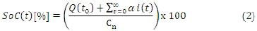
In addition to the alpha factor, the parameters in the formula are very intuitive. This is a factor used to describe performance, also known as Peukert's law [3] [4]. It describes the amount of lead acid battery at different discharge rates. When the discharge rate is increased, the available power of the battery will decrease. Another parameter that affects the available power is temperature. The higher the temperature, the higher the available power. Both performances use the alpha description, so the alpha value requires a 2-dimensional array (temperature and discharge rate). Based on the measured temperature and discharge rate, the corresponding values ​​are used for each integration step. The value of alpha depends to a large extent on the design and chemical composition of the battery, which is usually different even for different models of the same manufacturer. They usually pass the charging and discharging tests in the lab.
Although Peukert's law applies only to the case of discharge, there is also a performance factor similar to the alpha value for the charge cycle. In addition to temperature and charge rate, the actual SoC needs to be taken into account because the charging performance in the case of high SoC is less than that in the case of medium SoC.
Since the current value and the alpha value are combined, the error generated when the battery condition is changed, and the current measurement and quantization error become more and more with time. Therefore, the parameter Q(t0) (the starting point for current integration) is usually obtained by a different method that provides higher accuracy: the OCV method. OCV is the voltage between the two poles of a battery when no electrical components draw current from the battery.
Lead-acid batteries show a good linear relationship between OCV and SoC. Therefore, by measuring the OCV, the SoC can be calculated directly. The exact factor between OCV and SoC must be characterized.
The only drawback of this method is that the OCV can only be measured after the car has been parked, for example, after (almost) all electrical components are turned off, or after tens of minutes or even hours after the car is turned off.
Therefore, the OCV method is often used to calibrate coulomb counting, and the coulomb counting algorithm runs continuously. This combination provides a good SoC calculation method and can correct the SoC with self-discharge rate for a longer stopping time to make the calculation result more accurate.
3.2) Health Status (SoH)
The various aging effects of lead-acid batteries can have different effects on battery use [5]. Since it is difficult to monitor and quantify these aging effects one by one through IBS, the SoH rating is usually not directly tied to these aging effects. On the contrary, as the battery life increases, the capacity rating decreases, which is the main result of aging. Another very important parameter related to battery aging is startup performance; however, it is usually expressed as the functional status (SoF) of the startup capability (see Section 3.3).
Therefore, SoH is estimated by equation (3), where Caged represents the aged battery capacity and Cn represents the nominal capacity referenced in each SoC calculation.
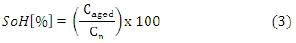
Because Cn is known, the key task in computing SoH is to find Caged. One possible approach is to track the maximum amount of power (or SoC) that can be reached throughout the life of the battery. If the maximum charge level of the battery is lower than the previously calculated aging capacity after several full charges that are subsequently performed, it means that the aging capacity becomes small. Correspondingly, Caged and SoH must be adjusted based on the capacity determined by the Coulomb count and OCV methods. The fully charged state can be monitored when the charge current drops below a certain threshold.
Another way to determine SoH is to track the charge and discharge cycles and take the rating from the battery manufacturer's cycle stability point. Typically, the manufacturer will ensure a total charge/discharge cycle at a specified temperature and depth, for example, 500 cycles at 27 degrees Celsius and 25% discharge depth. Tracking the above-mentioned Caged values ​​can be supported by rating all cycles to the above quantities and applying temperature and state of charge correction factors. These correction factors must be determined by characterizing the parameters of the battery. However, these two methods are often combined with other proprietary algorithms that take into account multiple battery parameters over the life of the battery.
A large number of battery parameter characterizations in the laboratory determine these battery parameters and are usually only available for a specific battery model.
3.3) Functional Status (SoF)
For lead-acid batteries, launching a car engine is a very important function, even if it is not the most important function. Therefore, a very important task for BMS is to predict whether a car can be started under actual power conditions. The startup prediction is represented by the SoF parameter.
In addition to the “traditional†parking after the past, it is becoming more and more important to start the forecasting function by introducing a start-stop system in the micro-hybrid. The BMS must communicate with the BCM and decide if it can be started again after the engine is shut down and if it is safe to enter stop mode.
A very good way to get SoF parameters is by analyzing the most recent engine start, remaining power (as a function of SoC and SoH) and actual temperature. During startup, the internal resistance (Ri) of the battery needs to be recorded (calculated by voltage drop and current). Because Ri is relatively consistent over the life of the battery and only rises significantly before the end of battery life, the Ri average needs to be below a certain threshold to ensure safe start-up. Another effect of aging the battery during the start-up phase is that the Ri value calculated from the voltage and current samples will exhibit a non-linear trend [5], ie different current values ​​for the same voltage sample. For new batteries, Ri is linear. See Figure 3 and Figure 4 for common voltage and current trends during startup.
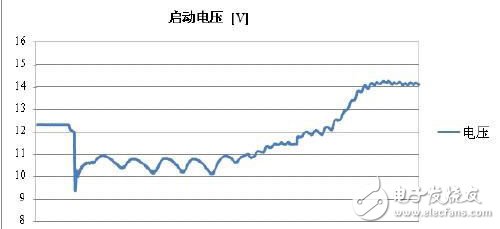
Figure 3: Startup voltage trend
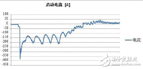
Figure 4: Startup current trend
The integrated Ri (calculated by voltage drop and current), the remaining battery power and the actual temperature provide a good indication of the starting capability. Again, these thresholds must also be determined by battery parameter characterization.
In order to determine the linear or non-linear behavior of Ri using the necessary exact values, all voltage and current values ​​sampled during the start-up phase need to be filtered using a linear filter, preferably with a pass filter.
4) Efficient implementation of BMS in hardware and software
Electrical energy efficiency is one of the most important features of a new type of car, supported by BMS. In addition to managing some of the power-saving features, the BMS needs to be energy efficient because it is one of the always-on systems that need to be powered by a lead-acid battery when the generator is not working. To meet this requirement, the energy consumption of the IBS must be as low as possible.
To achieve this goal, Freescale's IBS implementation uses two low-power models where the CPU and other hardware (HW) modules that do not need to be turned off can be turned off. In order to reduce energy consumption in normal operating mode and reduce customer software (SW) development work, additional hardware modules have been added to reduce software complexity. To achieve this, you can use a 16-bit microcontroller that is smaller, consumes less power, and is more cost-effective. Another way to reduce software complexity is to ensure product parameters throughout the life of the product and store factory calibration values ​​in non-volatile memory (NVM). As part of the product downline testing, these tuning values ​​are parameterized for each chip and stored accordingly. Therefore, there is no need to use complex calibration algorithms in the software.
In addition to the three technologies implemented in hardware, this chapter also introduces an efficient software implementation of the battery monitoring algorithm (see Figure 3).
4.1) Low power mode
Implementing a low power mode is a very good way to reduce power consumption. This is done by turning off the SoC component (especially the CPU) when it is not needed and changing it to normal mode only when needed (for example, activating all hardware modules). As mentioned earlier, there are two low-power models, the only difference being the program entry point used after the CPU is woken up.
However, in low power (ie no software interaction) mode, battery status needs to be monitored as well. First, the current needs to be tracked and the SoC is calculated by the coulomb counting method. Accordingly, current measurements (ie, coulomb counts) and automatic summation of current sample values ​​in low power mode can be supported.
The IBS must be able to react to battery and car status changes, ie the battery sensor must wake up in the event of various events. Accordingly, it is also necessary to measure the current and temperature during the low power mode. Current changes usually indicate a change in the state of the car (electrical components are turned on or off), and sometimes the temperature of the measurement channel needs to be recalibrated (see 4.3). The current and temperature sampled thresholds can be configured to trigger a wake-up if the threshold is exceeded. An automatic coulomb counter threshold wake-up mechanism can also be used.
In addition to those wake-up events for the measured parameters, other wake-up mechanisms can be implemented to allow the BCM or other electrical devices in the car to wake up the IBS (via LIN messages or direct wire connections), as well as a timed wake-up mechanism.
The implementation of the above low power modes and wake-up mechanisms allows IBS to run in low power mode (usually about 70%) most of the time, including engine runtime. SoC, SoH and SoF parameters will be recalculated during normal operating mode.
4.2) Migrating software tasks to hardware modules
Implementing dedicated hardware modules to take on the tasks in the software is an effective way to reduce software complexity and save power. Before using such hardware modules for battery monitoring algorithms, they can be used very efficiently for the pre-processing of voltage, current and temperature measurement samples. This is necessary because of the frequent interference in the wires of the car, and the measurement accuracy of the IBS sample values ​​is very high.
High-precision 16-bit sigma-delta ADCs with decimation and anti-interference filters are ideal for this application because of their high measurement accuracy compared to other ADC technologies. Combined with the error compensation function (see 4.3), it has been able to provide very good accuracy. However, it is often necessary to filter the samples again after the signal processing sequence. The reason for this is that noise in other electrical equipment in the car can be removed, so the frequency characteristics of the filter need to be freely converted. Another reason is that the specific battery parameters being observed are part of the battery monitoring and are closely tied to the excitation frequency (determined by the chemical composition of the battery). For example, Ri is the case. A programmable linear filter meets all of these requirements: filter coefficients can be transferred to the hardware filter module via registers. These registers can be programmed once and then no longer need to complete the filtering task in the software.
Current measurement results face a challenge because of the need for highly accurate measurements for small currents, while also supporting a wide range of measurements. The required accuracy is higher than 10 mA, which means a 1 μV drop across the 100 μOhm shunt; 1000A and higher currents occur during vehicle start-up. In order to support both of these needs while avoiding the need to perform manual measurement reconfiguration from software, an automatic gain amplifier needs to be implemented. An optional gain factor adjusts the input signal to optimize it to match the ADC's reference voltage. The adjustment of the gain factor can be done automatically, and the software does not need to be reconfigured throughout the run. A fixed gain factor can also be chosen for testing purposes or if there is a special application environment.
4.3) Simplified calibration work
A very important task to ensure high accuracy of the device throughout its lifetime is fine tuning and calibration. To this end, previously corrected correction factors can also be applied to critical equipment parameters. As part of the product line device testing, these factors are tested for different temperatures and stored in the NVM of the IBS. When the device is started, each trim parameter must be written to the device register by software. Parameters that require fine tuning can be found in the current and voltage measurement sequences. In addition, the oscillator, voltage reference, and LIN timing also need to be calibrated. Recalibration is also required during operation, such as the need to perform calibrations on a regular basis or to perform calibrations in the event of a sudden temperature change. If appropriate, different correction factors must be written to their respective registers.
The calibration function mentioned above avoids costly product downline testing for these parameters. In addition, the software complexity of the calibration can be reduced by simply applying the parameters.
4.4) Software implementation plan
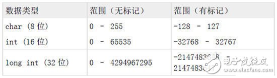
The battery management algorithms mentioned in section 3) require processor-intensive computation and control algorithms. Typically, model-based simulation tools are used on PCs to complete the first implementation of these algorithms. These tools typically use the floating point data format. These algorithms are imported into IBS in the later development process. However, due to cost and power consumption, floating-point hardware is not available on the microcontroller class used by IBS. Therefore, in order to achieve the applicable runtime, the data types used in the algorithm must be converted to a fixed-point integer format. There are a variety of data types and intrinsic value ranges available. For example, the following is a list of the types of data available on Freescale's IBS:
To represent a value less than 1, the LSB is mapped to a specific value.
This value is determined by the resolution required. By selecting one of the available data types, you can export a range of available values ​​for that variable and a virtual fixed decimal point (fixed dot format). For example, a resolution of 1 mV, using a labeled integer data type, ranges from 0 to 65.535 volts.
Because there is a 16-bit S12 CPU in Freescale IBS, the integer data type provides 16-bit precision. This means that 8-bit and 16-bit variables are processed to have higher performance than 32-bit values. Therefore, 8-bit and 16-bit variables are generally preferred.
From the algorithm implementation examples used to calculate SoC, SoH, and SoF mentioned above, it can be found that in many cases, 16-bit variables can provide sufficient value accuracy and range. This is because both voltage and temperature input values ​​have 16-bit accuracy (by using a 16-bit ADC). The other 16-bit precision is sufficient for the SoC, SoH, Ri, and correction factor α (see Chapter 3 for details). Even with 24-bit precision current samples, it can be mapped to 16 bits most of the time. At a precision similar to 3 mA, current values ​​in the +/- 98.3 A range can be represented by using a labeled 16-bit integer format without further modification to the digital format. This can meet the requirements of the car during driving and stopping. During startup, the current sample value will exceed the boundary and a 32-bit data format must be used. The parameters that require a 32-bit format are values ​​related to battery charging (eg, coulomb counters).
5) Summary
This white paper describes how to effectively implement BMS in a miniature hybrid vehicle using Freescale IBS. The most advanced battery state calculation algorithms (SoC, SoH, and SoF) are discussed. It can be seen from which special hardware features can be used in terms of power consumption to provide IBS efficiency. In addition, this article describes the use of low-power modes with automatic battery status monitoring (no software interaction required) and complex wake-up mechanisms. The results show that IBS can be in low power mode most of the time. In addition, with proper hardware signal processing, programmable filters, and simplified calibration, we can see that software complexity has been significantly reduced. This paper also introduces the principle of fixed-point algorithm. The results show that for the variables in the BMS algorithm, the 16-bit fixed-point data format can often meet the requirements, only in a few cases requires a 32-bit format.
A Buzzer or beeper is an audio signalling device, which may be mechanical, electromechanical, or piezoelectric (piezo for short). Typical uses of buzzers and beeper include alarm devices, timers, and confirmation of user input such as a mouse click or keystroke.
Buzzer
Piezo Buzzer,Dc Electro Magnetic Buzzer,Buzzer Acoustic Components,Piezo Buzzer For Thermometer
Jiangsu Huawha Electronices Co.,Ltd , https://www.hnbuzzer.com