Automotive electronics is an important symbol of the development of modern automobiles. The widespread use of automotive electronics has made modern cars more energy efficient, safer and more comfortable than ever before. However, when the internal electronic devices of the car are connected in a traditional point-to-point manner, the increasing number of electronic devices will lead to a substantial increase in the number of wires, resulting in an increase in the weight of the vehicle and impairing the performance of the vehicle. In order to meet the rapidly increasing demand of automotive electronic equipment, automotive electronic networks have emerged. The interior of the car has basically formed a complex network system from low speed to high speed, from cable to fiber, from wired to wireless, from discrete ECU data communication to central intelligent control. Among them, the hybrid network composed of low-speed CAN bus and LIN bus is receiving more and more attention and use in the connection of low-speed electronic equipment. As one of the important components of the car body, the car door lock realizes the car door lock unit based on the CAN/LIN network, which helps to improve the overall electronic level of the car body.
This article refers to the address: http://
The car door lock is one of the important parts of the car body. From the invention of the car, it has experienced the development process of mechanical, electrification and electronic. The electronic door lock of the automobile is an electromechanical integrated safety device controlled by an electronic circuit using an electromagnet, a micro motor and a lock body as an actuator. With the electronic door lock of the car, the driver can easily switch the door of the car without the metal key, and can effectively enhance the safety performance of the car door lock. Compared with the actuator, the electronic circuit part of the electronic door lock has great flexibility, so that the electronic door lock can be divided into a button type, a dial type, an electronic key type, a touch type, a biometric type and the like. Types of. Among them, the wireless remote control lock using the electronic key has the advantages of safety, reliability, and mature scheme, and is therefore often used as an electronic door lock for automobiles. The traditional electronic door locks are connected to other electronic devices of the car body in a point-to-point manner. With the trend of electronic network of automobiles, the electronic door locks of automobiles have gradually adopted a networked structure.
1 system structure of car door lock module
In this system, the car body control network adopts CAN/LIN hybrid structure, which can be divided into individual modules according to function: in addition to the door lock module, the body system also includes a seat module, a control panel module and a lamp group module. The modules are interconnected by a CAN bus, and each module is internally interconnected using a LIN bus.
The door lock module is an important part of the body electronics. Through the wireless remote control door lock managed by the main node, it is convenient to control the intelligent electronic control unit of each door, and timely feedback the node running status information, which greatly facilitates operation and maintenance. The automatic door lock unit includes a master node and a slave node (four door lock units), and its structure is as shown in FIG. 1.
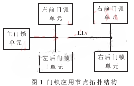
As the gateway of the door lock module in the body network, the master node forwards various control commands and body state data between the LIN bus and the CAN bus, so that the LIN bus and the CAN bus are seamlessly integrated into one.
Another major function of the master node of the door lock module is to manage the door lock. The door lock is controlled by radio remote control combined with button control. The button is installed inside the vehicle body. When the driver is inside the vehicle body, the door can be controlled by the button to open/close the lock. At this time, the control unit does not need to perform the unlock password check. In addition, the car lock can also be controlled by wireless remote control. The lock consists of a micro transmitter, a receiving antenna, and a microcontroller. The micro transmitter is mounted in a key handle, powered by a lithium battery and has a crystal oscillator circuit that delivers a stable carrier of approximately 40 MHz. The cryptographic signal generator provides an FM code. After receiving the signal, the antenna receiving device sends the signal to the signal receiver for amplification, frequency modulation, detection and signal waveform correction, and finally input to the comparison circuit for comparison with the password stored in the main door lock unit. , if it is consistent, execute the on/off lock.
The master node sends commands to each sub-door lock control unit through the LIN bus to control the on/off lock. After receiving the command, the child node triggers the motor drive mechanism to operate the door to unlock or close the lock. If 15 or more passwords are entered incorrectly within 10 minutes, the system assumes that someone is attempting to steal the vehicle and stops receiving any signals, including the correct password signal. After the system is locked, the driver must insert the mechanical key of the door into the lock hole to open the door. The system recovers from the locked state to the normal working state, which can be implemented by resetting the door lock control module. In addition, if the door is not opened after 30 seconds after unlocking, the door will be automatically closed.
The child node interconnects with the master node through the LIN bus, receives commands sent by the master node or returns feedback information. The actual door lock used is a motor-type automatic door lock, which is composed of a reversible motor, a transmission and a lock body assembly. The working principle is as follows: the gear rack is driven by the motor to drive the lock body assembly to lock or open the door. Therefore, the function of the door lock module sub-node is mainly to control the forward or reverse rotation of the reversible motor through the drive circuit to realize the on/off lock.
2 hardware design of car door lock module
The car door lock module consists of a master node and several child nodes, as shown in Figure 2. The communication between the master node and the child node uses the LIN bus. The LIN bus communication is based on the standard SCI (UART) hardware interface, single master multi-slave and does not require a stable time base. Only three wires are required (power line, ground line, data). Line), effectively reducing hardware costs. Microcontrollers generally have an SCI (UART) interface, so a LIN bus transceiver chip can be added to the periphery of the microcontroller to form a communication node on the LIN bus. The LIN bus transceiver uses Motorola's MC33399. The MC33399 is LIN compliant and can communicate digitally with multiple nodes in a medium speed network. Waveform correction reduces EMI interference. In addition, the MC33399 features a low current sleep mode and a dedicated wake-up input pin that allows the LIN control node to operate in a low-power mode [3].
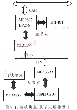
The microcontroller of the master node of the door lock unit uses the Motorola 16-bit microcontroller unit MC9S12DP256. The chip's internal modules include 16-bit CPU (HCS12 CPU), 256K bytes of Flash EEPROM, 12.0K bytes of RAM, 4.0K bytes of EEPROM, two serial communication interfaces (SCI), twenty-nine digital I /O channel, five CAN2.0 A/B software compatibility models (MSCAN12), etc. Therefore, the control node does not need to expand the storage unit, and the I/O resources also fully satisfy the requirements of the body control. The CAN communication interface can directly use the on-chip CAN module.
The remote control door lock uses NORDIC's nRF401 wireless transceiver chip. The nRF401 chip needs to expand fewer peripheral devices, and can directly connect to the serial port of the MCU to send and receive data without Manchester coding of the data, which reduces the difficulty of programming and use. The nRF401 chip uses a 4MHz crystal oscillator to generate an oscillation frequency, which is synthesized by a frequency synthesizer into a working frequency of 40MHz. The antenna is directly designed on the circuit board using a microstrip antenna, and is connected to the MC9S12DP256 through the Din and Dout interfaces.
The door lock unit sub-node microcontroller uses PHILIPS' low-cost FLASH microcontroller P89LPC904. The P89LPC904 comes with 1KB of Flash program memory, 128 bytes of RAM data memory, a high-precision internal RC oscillator (no external oscillator required), and an 8-bit A/D input with two channels. At the same time, it has two different power-down modes of power-down and power-down. When the LIN bus is idle, the system can switch to power save mode.
Since the small motor is to be driven in the application, the door lock unit requires the use of Motorola's H-bridge motor drive chip. The output interface of the microcontroller cannot directly drive the motor. It is necessary to provide the drive capability of the door lock unit through the power IC chip of the MC33887. During the motor drive process, the current value is also converted into a voltage signal and fed back to the P89LPC904 for fault detection in the door lock control.
3 software design of the car lock module
The system software design includes two parts: the master node and the child node.
The master node of the car lock module receives the control command of the body network total control unit through the CAN bus, and returns the switch state and fault information of the current car lock. At the same time, it sends control commands to the child nodes of the car lock module to receive status information. The master node needs to perform appropriate conversion of the data frames between the CAN and LIN buses.
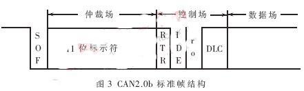
The CAN bus in the system communicates in the CAN2.0B standard frame format. The standard format CAN2.0B data frame includes three parts: arbitration field, control field and data field. The SOF (Frame Start) marks the beginning of the data frame and the remote frame and consists of one display. The arbitration field consists of an identifier and an RTR (Remote Send Request Bit). The RTR is a bit in the data frame and must be a hidden bit in the remote frame. The identifier of the master node of the door lock unit is 0x50. In the control field, the IDE bit of the standard frame is the display bit, r0 is the reserved bit, and the DLC is the data length code [4]. The CAN2.0B standard frame format is shown in Figure 3.
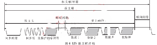
The LIN bus communication is performed through the message frame, and the message frame format is as shown in FIG. The synchronization gap indicates the start of a new message frame, and the synchronization gap is generated by the main task (within the master node). The byte field of the sync field is 0x55. From the task, the sync gap and the sync field byte stream can always be detected. If a new sync gap, sync field is detected, the ongoing transfer task is aborted and a new message frame transmission is initiated. The identifier of the packet header consists of 6 bits and ranges from 0 to 63. Except for a few reserved specific uses, it can be used as a communication ID, and the identifier assignment of the LIN node in the door lock unit is as shown in Table 1.
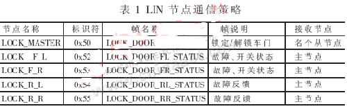
The master node sends a LOCK_DOOR frame to each door lock unit via the LIN bus, including a lock/unlock command for the door lock. After receiving the message frame, the child node parses the data field in the frame. The first byte in the data field marks the unlock command, bit0 corresponds to the left front door, bit1 corresponds to the right front door, bit2 corresponds to the left back door, and bit3 corresponds to the right back door. The second byte marks the lock instruction, and the correspondence is the same as the unlock command. The two backdoor locks LOCK_R_L and LOCK_R_R send response frames LOCK_DOOR_RL_STATUS and LOCK_DOOR_RR_STATUS to feed back the fault information of the system fault and the door lock motor execution to the master node. In addition to transmitting this information, the two front door locks also send the door lock switch status information to the master node, and the master node can use this information to generate the lock/unlock command again.
In addition, after receiving the remote frame of the main control unit of the vehicle body through the CAN bus, the master node needs to reply to the data frame to notify the current control unit of each door lock state. When the door lock unit is in a deadlock state due to the input of the wrong password, after receiving the reset command frame of the overall control unit, the master unit of the door lock unit resumes receiving the password signal.
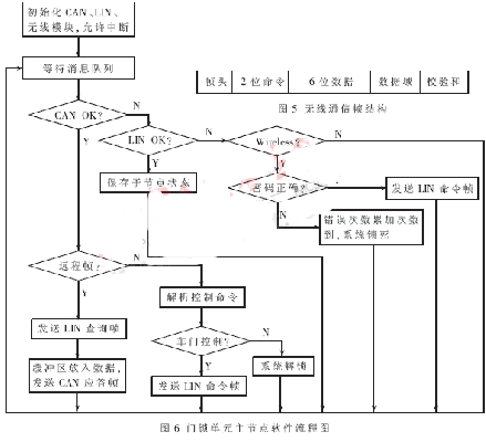
The remote door lock and the key are opened/closed by a simple communication protocol, including a byte header 0x80, a 2-bit command, a 6-bit frame length, a data field, and a checksum. For the data field of the remote on/off lock command, that is, the on/off lock command password, a certain encryption is required. In fact, the remote control door lock and the key each hold a key, the key first obtains a randomly generated key from the remote door lock, and then encrypts the door code with the key and the key, and then sends it to the remote door lock. The remote control door lock decrypts the received data according to the key and the key, and obtains the password and verifies the correctness. Based on security and reliability considerations, a series of processes such as sending a key and sending a password are based on connected communication. The remote control switch lock command frame format is shown in Figure 5. The command field is divided into: 0x00 request to obtain the key, 0x01 to send the password to unlock, 0x02 to send the password to lock.
The master application is based on the μC/OS real-time operating system. The μC/OS real-time operating system has been ported to the MC9S12DP256 microcontroller. The μC/OS core is small and efficient, and has low system performance overhead. Moreover, multi-tasking-based operating system development applications can make development faster and easier. Enhanced portability. The function of the master node is divided into different tasks and executed independently. After completing the initialization of the CAN, LIN communication interface and the nRF401 chip, the master node creates the task processes OS_CAN_PROCESS, OS_LIN_PROCESS, OS_WIRELESS_PROCESS and waits for the semaphores to obtain the semaphores and then perform their respective operations. Among them, the semaphore they wait for is sent by the corresponding interrupt handler, driving each task to execute, and after waiting for the task, continue to wait on the semaphore. OS_MAIN_TASK is the main task of the master node, waiting for the message queue to distinguish different operating states according to the returned message.
OS_CAN_PROCESS and OS_LIN_PROCESS are the data receiving tasks of CAN and LIN bus. After receiving the data, they are put into the buffer, set the status bit, and then notify OS_MAIN_TASK through the message queue for proper processing. CAN and LIN bus data transmission is directly initiated by OS_MAIN_TASK.
OS_WIRELESS_PROCESS manages the connection for wireless communication. The wireless connection has multiple states, including LISTEN, CONNECTED, FIRST_SEND, CLOSED, etc., which represent waiting for connection, connection establishment, clear key transmission, and connection closure. When the wireless connection state is switched, OS_MAIN_TASK needs to be notified through the message queue, and the main task performs management control according to different connection states. The OS_MAIN_TASK task flow is shown in Figure 6.
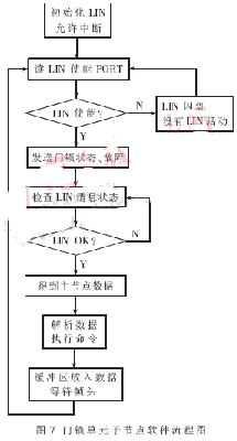
The child node program is relatively simple, and the ability of the child node to control the chip is weak, so the program design is based on the front-end and back-end modes. After receiving the command frame of the master node through the LIN bus, the child node drives the motor on/off lock through the drive circuit. Monitor the motor current during the on/off lock, check for faults, and return to the car door lock status information and fault conditions. The workflow of the child node is shown in Figure 7.
With the development of electronic networking of automobiles, low-cost LIN networks will be more and more widely used. The automatic door lock control module based on CAN/LIN hybrid network introduced and implemented in this paper is a typical application in automobile body control. It improves the overall automation degree of the vehicle body and has a good application prospect.
Cordless Floor Cleaner is a new and smart vacuum mopping cleaner. recharge floor cleaner very small,free,simple use. Latest floor wipe cleaner can vacuum ,mopping,wipe home,hotel,office clean area.recharge mopping cleaner very good design,use simple and freely,
Wireless hand floor cleaner advantage:
Cordless hand floor cleaner with special design and best quality
Vacuum ,mopping function
Fast and silent and smart floor hand cleaner
Cordless floor cleaner facotry in shenzhen,china,welcome to visit facotry,we are 15 years manufacture experience.
Cordless Floor Cleaner
Cordless Floor Cleaner,Robot Vacuum Cleaner,Cordless Hard Floor Cleaner,Cordless Floor Cleaning Machine
Zhengzhou Bangmi Smart Technology Co., Ltd. , https://www.globalcleanrobot.com