0 Introduction High-resolution visible light camera is one of the most important means of aerospace remote sensing, and has wide application prospects in both commercial and scientific research fields. The development of high-resolution visible light cameras has become an important indicator of a country's scientific and technological level. At present, the requirements of users for ground resolution are constantly increasing, and the development of high-resolution optical remote sensors has become a hot research topic in the field of space remote sensing in countries around the world. High-resolution visible light cameras have developed early in foreign countries, and developed countries such as the United States have successively developed high-resolution visible light cameras. However, the development of China's high-resolution CCD camera started late, and there is still a certain distance from the level of developed countries. There are many factors that affect the resolution of the camera. Low-noise video processing technology is one of the keys to achieve the high-resolution imaging capability of the camera.
1 Noise and noise processing of CCD device
The noise of the CCD device mainly includes photon noise, shot noise, fat zero noise, transfer noise, dark current noise and output noise [1]. Noise is the main factor affecting the CCD output image signal.
In the CCD application, the following measures have been taken to suppress and eliminate the above noise [3]:
(1) In the circuit technology, increase the filtering of the DC power supply to eliminate interference from the power supply. Shorten the connection between the drive circuit and the CCD device to reduce the spike interference caused by clock sensing. The digital ground is separated from the analog ground to reduce interference from the ground wire.
(2) For the transfer noise, inverting the CCD voltage or increasing the substrate voltage to invert the CCD voltage can eliminate the interface state capture noise; lowering the operating temperature can significantly reduce the capture noise exponentially.
(3) For shot noise, use the adjacent pixel (or adjacent line) integral averager method to remove or the adjacent multi-frame average method. (4) Dark current noise: For a CCD with a relatively dark current of each pixel, if there are a small number of dark pixels at the beginning of the pixel array, the output signal is sampled and stored, and the subsequent effective pixel The output signal samples are subtracted to remove dark current noise. But it must be ensured that the integration time and temperature of the two samples are the same.
(5) For the output noise, a low-pass filter with a cut-off frequency of 2f (f is the CCD readout frequency) can be used. In addition, there are related double sampling method (CDS), double oblique integration method (DSI), clamp removal method (CCS) and so on.
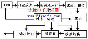
2 TDICCD video signal processing The video processing circuit is mainly to remove the reset pulse interference and noise signal, which consists of pre-amplification, related double sampling, clamping, filter output, line buffer, output interface circuit and other links. The CCD video processing circuit is shown in Figure 2-1.

Figure 2-1 Block diagram of video processing circuit
The image signal received by the CCD image sensor is pre-amplified to be a differential signal output, converted into a single-ended video signal after a differential receiving circuit, and subjected to CDS to perform correlated double sampling processing to obtain a "clean" video signal, which is then low-pass filtered The filter removes the spike interference of the CCD drive pulse, is amplified by the controllable gain amplifier circuit to the level required by the A / D converter, performs A / D conversion, becomes a digital image signal, and is alternately buffered by the buffer (FIFO). LVDS interface chip output after driving.
In the actual design, Philips' special CCD camera interface chip TDA8783 is used to achieve.
2.1 Introduction to TDA8783
TDA8783 is a 10-bit analog-to-digital interface chip dedicated to CCD cameras of PHILIPS Company. It is mainly composed of related double sampling circuit (CDS), gain control circuit (AGC), clamping circuit, and low-power 10-bit analog-to-digital converter (ADC ) Composition [5]. The functions of the system can be completed by programming the on-chip three-wire serial port to realize the distribution of on-chip DACs.
2.2 Preamplifier circuit
The signal level output by the CCD decreases as the accumulated charge increases. In order to carry out long-distance transmission and reduce the common-mode interference introduced during transmission, amplification and differential output are required. The pre-amplification function is to amplify the output signal of the CCD to a sufficient amplitude.
In this system, the AC coupling mode is used between the preamplifier and the CCD output, which eliminates the DC level, which is beneficial to the matching between the two stages, and also eliminates the influence of temperature and other factors on the transmission signal caused by zero drift. Of course, the use of AC coupling will cause the loss of the DC component in the signal, which can be recovered by the subsequent clamping circuit.
2.3 Correlated Double Sampling (CDS)
In order to ensure the output of video signals with high signal-to-noise ratio, the noise must be dealt with. Correlated Double Sampling (CDS) technology can not only filter out the reset noise, but also filter the horizontal clock drive of the TDICCD sensor and the power ground coupling noise, white noise and 1 / f noise of the output amplifier. In addition to the role [4].
In this system, we use the CCD camera interface chip TDA8783 to realize CCD video signal processing. It contains a correlated double sampling (CDS) module, which can effectively process the CCD output signal and eliminate the KTC noise of the CCD. CDS programmable bandwidth is 4 ~ 120MHz; input peak voltage is 400mV; output amplifier gain is 6dB. In use, the CDS function can be realized by programming the external three-wire serial port to select the internal control DAC. When the serial port shift register address A2A1A0 = "001", the on-chip 4bit DAC works to control the CDS. The sampling rate in this system is 4MHz, and the input code of the 4-bit DAC is set to D3D2D1D0 = "0001".
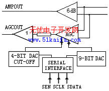
2.4 Gain control In order to adapt to different brightness targets and prevent the signal from being too weak or saturated, a gain selection amplifier circuit should be designed in the video signal processing circuit. According to the brightness of the ground target, select the corresponding gain. A gain controller (AGC) is integrated inside the CCD camera interface chip TDA8783. The minimum gain of the AGC output is 4.5dB, and the maximum gain is 34.5dB. The internal logic relationship of gain control of TDA8783 is shown in Figure 2-2. The gain control function is realized by programming the three-wire serial port. When the serial port input shift register address A2A1A0 = "010", 9 bits control the DAC; when the input code is "00", the minimum gain is 4.5dB, and the input code is greater than When equal to "319", the output gain is 34.5dB. 
Figure 2-2 Internal logic relationship diagram of gain control
2.5 Clamp and filter circuit

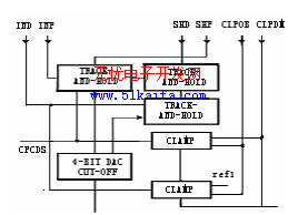
Figure 2-3 Internal logic block diagram of input clamp
The signals output by the correlated double-sampling processing circuit are mixed with sampling spike interference and other high-frequency interference signals. This requires a low-pass filter circuit to filter out high-frequency interference and select useful video signals with lower frequencies. At the same time, the preamplifier adopts AC coupling, and the negative-polarity AC signal undergoes correlated double sampling to remove noise, and appears in the form of positive polarity at the output of the correlated double sampling circuit. During the two sampling and subtraction process, some unnecessary negative components will be introduced. Since the A / D conversion circuit requires that the input analog quantity cannot be negative, a clamping circuit is provided to remove the negative level in the signal after low-pass filtering.
The TDA8783 includes a bandwidth control circuit and a clamp control circuit. The bandwidth control and clamp control functions can be realized by programming the on-chip three-wire serial port. The internal logic relationship of the clamp control of TDA8783 is shown in Figure 2-3. When the serial port input shift register address A2A1A0 = "001", the on-chip 8 bit DAC works to control the bandwidth, at this time D3 ~ D0 are used to set the CDS bandwidth, D4 ~ D7 are used to set the AGC bandwidth; when the serial port enters the shift register address When A2A1A0 = "100", the on-chip 10bit DAC works to control the input clamp level of the ADC (analog-to-digital converter).
When the input code is "0", VDACOUT (ADC clamping control DAC output voltage) is 1.5V; when the input code is "1023", VDACOUT is 2.5V.
2.6 The output of the analog-to-digital conversion video processing circuit is an analog signal. In order to facilitate data compression and transmission, it needs to be converted into a digital signal. The analog-to-digital conversion circuit [2] converts the analog video signal into a digital video signal under the control of timing pulses. And drive the output according to the prescribed format. According to the requirements of the technical indicators, the radiation quantization level is 8bit, and it is necessary to use the A / D chip output with a sampling rate greater than 10MHz. In order to obtain high-quality quantized signals, it is necessary to carefully select A / D converters with higher performance parameters.
In this system, TDA8783 integrates a 10-bit A / D converter. The maximum sampling frequency of the ADC (analog-to-digital converter) can reach 40MHz, the minimum clock pulse width is 12ns, the duty ratio is 1: 1, the input peak voltage is 2V, the maximum input current is 120, + 5V single power supply, the typical nonlinear error is 0.2LSB , The maximum sampling delay is 5ns.
When performing A / D conversion, it is necessary to correctly determine the sampling point of the A / D conversion, that is, the position of the sampling pulse on the analog signal (the sampling point must be placed on an effective and stable analog signal segment), otherwise it may be If the sampling point falls on an unstable position of the signal, an error signal is generated, or if the sampling point falls on a position other than the signal, an error signal is generated.
2.7 Data output interface Data output adopts LVDS differential output. The output signals of each channel are: one channel of pixel clock, one channel of line synchronization signal and digital image signal. The image data, line synchronization and pixel clock signals are output after being driven by the interface circuit. The interface chip selects DS90C031 of NS company.
3 Conclusion (1) Only the correct design of the timing drive signal of the system can complete the coordination of the entire circuit;
(2) The pre-amplifier circuit of the CCD output video signal should also be as close as possible to the sensor, CCD video signal processing circuit
It should also be as close as possible to reduce the noise interference introduced during transmission;
(3) After the CCD signal is processed by the video processing circuit, the signal quality has been greatly improved to meet the system index requirements.
Shenzhen Dituo Electronic Co.,Ltd. is the China leading manufacturer and supplier of Ultrasonic Diffuser, Ultrasonic Essential Oil Diffuser, and we are specialize in Ultrasonic Aroma Diffuser,Essential Oil Diffuser, etc.
The Ultrasonic Diffuser dissipates water molecules and dissolved essential oils into nanometer-grade cold mists with a diameter of 0.1-5 micrometers in the surrounding air through the high-frequency oscillation generated by the ultrasonic vibration device, so that the air is full of fragrance. After heating in winter, the indoor air is dry, people will have dry lips, dry throat, dry mouth, dry skin, nose bleeding and other "heating dry" symptoms, Ultrasonic Essential Oil Diffuser uses a variety of ways to atomize water and pure plant essential oils, so that the room maintains a high humidity and produces a certain amount of natural negative oxygen ions to purify the air while achieving the effect of aromatherapy.
Ultrasonic Aroma Diffuser is a fashion, a culture, and a spiritual sustenance for people who pursue high-quality life.
Ultrasonic Diffuser
Ultrasonic Diffuser,Ultrasonic Essential Oil Diffuser,Ultrasonic Aroma Diffuser,Essential Oil Diffuser
Shenzhen Dituo Electronic Co.,Ltd. , https://www.sz-dituo.com