FM wireless microphone manufacturing method
Every electronic lover has the experience of electronic production, from the continuous failure at the beginning to the gradual handy, the taste is beyond the reach of outsiders. In fact, there are many friends who want to enter the gate of electronic production, but they are hovering outside because they cannot find a way to get started ~~
The practicality of electronic technology is extremely strong. It is a good way to quickly get started by assembling and debugging the production kit. The electronic production laboratory website is ready to use the website as a multimedia platform to display the entire process of making the kit in text, pictures, etc. Improve the success rate of production, and intersperse some basic component knowledge in the production process to help beginners complete the production. Here we have carefully selected several varieties that have been promoted and used in many schools. Students reflect that these small productions are interesting, they can learn knowledge, and they can bring students extra energy to the right track. Maybe they can still make a living in the future. Craftsmanship.

Making a FM wireless microphone by yourself is not only easy but also very interesting. I believe that many electronics enthusiasts have done it by themselves, and the webmaster is no exception. I made it 6 years ago and used it to joke with friends ~ ~~
Here we provide a set of more typical FM microphone production kits, which includes all the components used to make FM microphones. As a beginner or a newcomer, you can learn some related knowledge by making kits, especially for students. The theoretical knowledge already has a little, but it is another matter to start with it ~~
Principle analysis of wireless microphone:
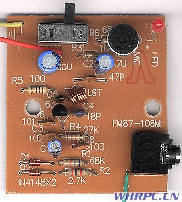
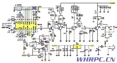
The following is the circuit diagram of the FM wireless microphone. The circuit is very simple and there are no extra components. The high-frequency transistor V1 and the capacitors C3, C5, and C6 form a capacitive three-point oscillator. For beginners, we don't want to think about the specific working principle of the capacitor three-point type for now. We only need to know that this circuit structure is a high-frequency oscillator. The load C4 and L of the triode collector constitute a resonator. The resonance frequency is the transmission frequency of the FM microphone. According to the parameters of the components in the figure, the transmission frequency can be between 88 and 108MHZ, which just covers the receiving frequency of the FM radio. By adjusting the L The value (stretching or compressing coil L) can easily change the transmission frequency, avoiding FM radio. The transmitted signal is coupled to the antenna through C4 and then transmitted.
R4 is the base bias resistor of V1, which provides a certain base current to the transistor, so that V1 works in the amplification region, and R5 is a DC feedback resistor, which plays a role in stabilizing the working point of the transistor.
The frequency modulation principle of this FM microphone is to achieve frequency modulation by changing the capacitance between the base and the emitter of the triode. When the sound voltage signal is applied to the base of the triode, the capacitance between the base and the emitter of the triode The size of the sound voltage signal changes synchronously, and at the same time the transmission frequency of the transistor changes, so as to realize frequency modulation.
The microphone MIC can collect external sound signals. Here we use a small electret microphone, which has a very high sensitivity and can collect weak sounds. At the same time, this microphone must have a DC bias to work, and resistor R3 can provide a certain DC bias voltage, the greater the resistance of R3, the weaker the sensitivity of the microphone to collect sound. The smaller the resistance, the higher the sensitivity of the microphone. The AC sound signal collected by the microphone is matched with C2 and matched with R2 and then sent to the base of the transistor. The conduction voltage of the diode is only 0.7V. If the signal voltage exceeds 0.7V, it will be shunted by the diode. This can ensure that the amplitude of the sound signal can be limited to plus or minus 0.7V. Excessive sound signal will cause the transistor to pass Modulation, producing sound distortion or even not working properly.
CK is an external signal output socket. You can introduce an external sound signal source such as a TV headphone jack or a Walkman headphone jack into a FM transmitter through a dedicated connection line. The external sound signal is attenuated by R1 and limited by D1 and D2 and sent to the triode base. Frequency modulation. So this kit can not only be used as a wireless microphone, but also as a TV wireless headset.
The light-emitting diode D3 in the circuit is used to indicate the working state. It will light up when the FM microphone is powered on, and R6 is the current-limiting resistance of the light-emitting diode. C8 and C9 are power supply filter capacitors. Because large capacitors are generally made by winding process, the equivalent inductance is relatively large. Paralleling a small capacitor C8 can reduce the high-frequency internal resistance of the power supply. This circuit is very common.
In the circuit, K1 and K2 are actually a switch. It has three different positions. When it is dialed to the far left, the power is turned off. On the far right, K1 and K2 are connected to be used as FM microphones. The middle position is K1 on and K2 off. Used as a wireless transponder, because the microphone does not work as a wireless transponder, but the microphone consumes a certain static current, so disconnecting K2 can reduce power consumption and extend the life of the battery.
Hands-on hands-on wireless microphone:
Note: The FM kit described on this page is not available on this website, please do not ask!
7. The high-fidelity stereo digital phase-locked loop 5W FM transmitter module FM7 using BH1417 is out of stock and needs to be ordered and supplied!

Debugging method: (without oscilloscope and other instruments)
1 After the welding is completed (reserved an inductor of the collector of 1917, do not weld L9 or L8 first)
2 First debug the 1417 part, solder a wire about half a meter long from the 11th pin of 1417 as the antenna. Disconnect the capacitor C31. Set the DIP switch to a frequency, now suppose it is set to 88.3M, and at the same time the radio reception frequency is also 88.3M. When ready, input a stereo music signal. Pass 12V DC (note the positive and negative levels) to adjust the inductance L3 At the same time, pay attention to whether there is the music you put in the radio. If the music you put appears, test the voltage of the connection point of R4 and R3 with a digital multimeter. At the same time, adjust the inductance L3 to make this voltage 2V- Between 3V, at the same time the radio should be able to receive this frequency. The commissioning of part 1417 is completed.
3 Make a simple field strength meter, the circuit is as follows:
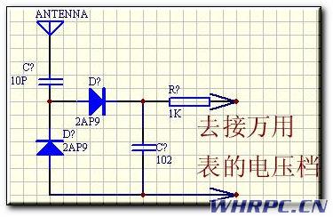
First debug the front part of 1971, remove the 11-pin antenna of 1417, weld the capacitor of C31 to clamp the input terminal (ie antenna) of this field strength meter to the base of 1971 with a metal clip, and debug L1, C04 in turn, so that The display of the multimeter is the largest, and then debug C03, C02, L6 in turn, which is also to make the display of the multimeter the largest. After the end, weld the inductance without welding. Note that when debugging the 1971 part, the power supply voltage is reduced to 8-9V, and a 50-ohm antenna must be connected. It is recommended to use a GP antenna.
4. Commission the 1971 part, connect a 50 ohm antenna, and connect with a 50 ohm cable, the cable should not be less than 4 meters. The input of the field strength meter is connected with an antenna next to the antenna at a distance of about 2 meters. Connect 1971 to the heat sink. After preparation, turn on C00 and C01 and pay attention to the sound in the radio to make the sound clearest and the indication of the field strength meter is the largest. Then fine-tune C02 and C03 to make the sound clearest and the indication of the field strength meter the biggest. At this time, the voltage can be adjusted to 12V and the work adjustment is completed.
Make your business brand or logo stand out in ways common signage simply can`t match!
A great way to make your company name, logo or promotional message stand out, custom Neon Sign Logo is a specialty.
Neon Sign Logo
Neon Sign Logo,Custom Led Logo,Light Up Logo Signs,Led Logo
Shenzhen Oleda Technology Co.,Ltd , https://www.baiyangsign.com