Over the past few decades, Controller Area Network (CAN) applications have moved from primarily using 5V protocol controllers to mostly including 3.3V controllers. However, the use of 5V CAN transceivers is still very common, so CAN transceiver applications that are paired with a 3.3V controller and a 5V transceiver are often seen. Some of the problems in this setup can be addressed by using a 3.3V CAN transceiver in a particular application.
Mixing the controller and transceiver supply voltages together in one application requires at least one regulated supply rail for each voltage. In some cases, just to support a 5V transceiver, it adds cost, board space, and overall design complexity. For these applications, switching the CAN transceiver to a 3.3V rail can alleviate this problem.
Figure 1 shows a block diagram of a dual power rail application using a 5V transceiver and a 3.3V controller. Figure 2 shows a simpler setup that is possible when the CAN transceiver and controller are both powered by 3.3V.
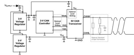
Figure 1: Dual Power 5V CAN Transceiver Application 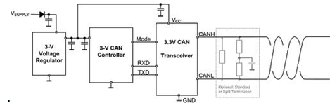
Figure 2: Single Supply 3.3V CAN Transceiver Application
A common concern is the difference in common-mode bias voltages for 5V and 3.3V CAN transceivers, and the communication problems that can result. Fortunately, this problem has been solved by the ISO18898-2 standard, which requires the receiver portion of a CAN-compatible transceiver to handle a common-mode range of -2V to +7V. This requirement was further extended to the ±12V range in the ISO11898-5 standard release.
Figure 3 shows a 3.3V transceiver (typically biased to 0.7*Vcc to meet the 2V and 3V CAN standards), a common-mode bias voltage range for 5V transceivers, and a total of two CAN standards required Mode input range. In addition to the common mode offsets caused by mixed 5V and 3.3V CAN transceivers, there are still many large common mode offset margins. Since the common mode offset is not a serious problem, this achieves interoperability.
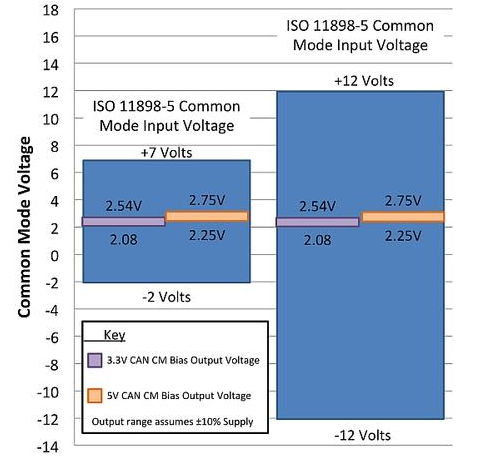
Figure 3: CAN Common Mode Range
When setting the common-mode bias voltage of a 3.3V CAN transceiver to any value other than 0.5*Vcc, it is important to note that the device exhibits a common-mode shift when transmitting. This displacement occurs because the drive strengths of the high-end and low-side drivers are substantially the same, so that the dominant bit obtained is at the center of Vcc/2. A common mode shift of 0.7*Vcc to 0.5*Vcc occurs whenever a 3.3V transceiver transitions between recessive and dominant bits (Figure 4).
The displacement of the common mode voltage creates harmful conduction and radiation emissions on the bus. To eliminate these emissions, a separate termination can be placed on the bus to filter common mode noise (Figure 5). This filter can be adjusted by changing the value of the capacitor.
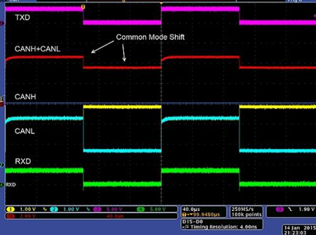
Figure 4: Common Mode Displacement of a 3.3V CAN Transceiver 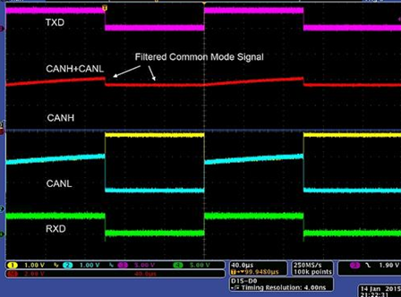
Figure 5: Common Mode Filtering
Another common problem with adding 3.3V CAN transceivers is that their output differential voltage is less than the output differential voltage of the 5V CAN transceiver, so noise immunity is low. The CAN standard addresses this issue by requiring all transceivers to drive an output differential voltage of at least 1.5V and requiring the receiver to have an input threshold voltage set to a 0.9V differential voltage. Therefore, as long as the 3.3V transceiver is capable of driving the lowest voltage of 1.5V, a voltage margin of 0.6V is formed in the system to cope with line loss and noise margin. To compensate for the reduction in voltage headroom, the size of the driver in a 3.3V transceiver is typically larger than the driver in a 5V transceiver.
In summary, many people mistakenly believe that 3.3V and 5V CAN transceivers cannot be mixed together in the same network, or that a robust 3.3V CAN network cannot be built. This is not the case. More than 10 years after its launch, 3.3V CAN transceivers are still popular in devices such as large appliances, server backplanes, smart grids, and battery-powered devices because they simplify end product design. With this in mind, and always paying attention to common mode emissions, the 3.3V CAN transceiver can be used in more and more advanced applications.
1.ANTENK FEMALE HEADER Series Receptacle Strips are a series of sockets offered in a multitude of sizes and profiles designed to satisfy most .100" pitch socket requirements. Available in Single, Dual and Triple row, they are offered in Straight, Right Angle, SMT, Bottom Entry and Pass Through PCB mounting styles. Each type has a specially designed contact system which uses a wiping mating action and produces a high normal force connection with gold, tin or selective gold plating. All are available with Standard or Hi-Temp Thermoplastic insulators. Our SMT offering is available with optional pick and place pads and tape & reel packaging.
2.Our products are widely used in electronic equipments,such as monitors ,electronic instruments,computer motherboards,program-controlled switchboards,LED,digital cameras,MP4 players,a variety of removable storage disks,cordless telephones,walkie-talkies,mobile phones,digital home appliances and electronic toys,high-speed train,aviation,communication station,Military and so on


2.54 Famale pin headers
SPECIFICATION
Current Rating: 3.0 Amp
Insulation Resistance: 1000M ohms min
Contact Resistance: 20M ohms max
Dielectric Withstanding: AC500V
Operating Temperature: -65°C to +125°C
Contact Material: Brass
Insulator Material: PBT,UL 94V-0 Black
Female Pin Headers,Pcb Female Connectors,Pin Connector Header,Oem Female Header
ShenZhen Antenk Electronics Co,Ltd , https://www.antenk.com