Performance comparison of integrated RF mixer and passive mixer solutions
Abstract: This application note compares the overall performance of integrated RF mixer and passive mixer solutions, discusses the main features of the two solutions, and points out the main advantages of integrated solutions over passive solutions.
In the past, RF developers used passive down-conversion mixers in high-performance receiver designs to achieve good overall linearity and spur performance. But the use of discrete passive mixers in these designs also has some disadvantages.
In order to meet the requirements of the overall noise figure of the receiver, the insertion loss of the passive mixer needs to be compensated at the radio frequency (RF) gain stage or intermediate frequency (IF) gain stage. Compared with the integrated mixer, when using a passive mixer, users should not only consider their input third-order intercept point (IIP3), but also consider the output third-order intercept point (OIP3). The second-order linearity index of passive mixers is generally worse than that of integrated balanced mixers, and this index is very important when considering the half-IF spurious performance of the receiver. Because the linearity of the mixer is directly related to the drive level of the local oscillator, a considerable local oscillator injection must be generated and then fed into the local oscillator port of the passive mixer through the PCB wiring. In addition, an external RF amplifier stage is required to amplify these signals, making the entire design very sensitive to local oscillator radiation and interference. Since the passive mixer is a fully discrete solution, the cost is higher and the PCB size is larger. The deviation between the discrete components can also cause differences in performance.
The integrated (or active) mixer design can achieve performance comparable to passive mixers, and is therefore very popular. The integrated mixer consists of a true balanced mixer (Gilbert unit) or a passive mixer with intermediate frequency amplification, which compensates for losses with gain. Because the integrated mixer has a gain stage, it no longer requires an external IF amplifier to compensate for losses like a passive mixer. For integrated mixers with very good noise figure specifications, such as Maxim's MAX9993, MAX9981, and MAX9982, a smaller RF gain is required at the front end of the mixing circuit, thereby improving the overall linearity of the receiver. It is worth emphasizing that if the series noise figure is improved by increasing the gain at the front end of the mixer, the linearity of the mixer must also be improved to maintain the overall linearity of the receiver. Maxim's MAX9993, MAX9981, and MAX9982 mixers also include local oscillator (LO) drive circuits.
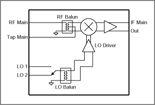
Maxim's MAX9993 high linearity down-conversion mixer has the functions shown in Figure 1: 
Figure 1. MAX9993 equivalent circuit
The specifications of MAX9993 in the PCS and UMTS bands are as follows:
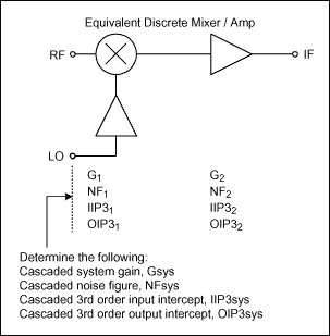
Figure 2 shows a discrete solution consisting of a passive mixer, intermediate frequency amplifier and LO amplifier. The single-ended component is used in the figure, and its second-order linearity is worse than Maxim's integrated mixer. From the data sheet of the integrated RF mixer, in order to compare with Maxim's integrated mixer, RF circuit designers must consider the equivalent series characteristics of individual discrete components in the passive design. For example, designers should not only pay attention to the third-order input intercept point of the passive mixer, but also consider its third-order output intercept point and the overall system response including the intermediate frequency amplification stage. In addition, the designer must also calculate the equivalent gain and noise figure of the passive mixer scheme and compare the results with the integrated mixer parameters. 
Figure 2. Discrete mixer / IF amplifier
The following symbols are used for each level of circuit:
G = frequency conversion power gain
NF = noise figure
IIP3 = input third order intercept point
OIP3 = output third-order intercept point
For an example, refer to Figure 2 and calculate the parameters of the intermediate frequency amplifier to obtain an overall series response equivalent to the MAX9993 gain, noise figure, and third-order intercept point performance. Assuming that the Mini-Circuits® HJK-19MH passive mixer is used in the PCS and UMTS bands, the given parameters are:
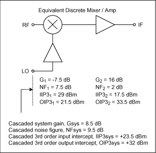
G1 = -7.5dB
NF1 = 7.5dB (Assumption)
IIP31 = + 29dBm
OIP31 = IIP31 + G1 = + 21.5dBm
Take the typical index of MAX9993 as the typical parameter of PCS and UMTS bands:
Gsys = total system gain = + 8.5dB
NFsys = System noise figure = 9.5dB
IIP3sys = System input third-order intercept point = + 23.5dBm
OIP3sys = System output third-order intercept point = + 32dBm
Required IF amplifier gain:
The gain of the intermediate frequency amplifier is determined by the following formula:
Gsys = 8.5dB
G2 = Gsys-G1 = 8.5dB-(-7.5dB)
= 16dB
IF amplifier noise figure required:
In order to obtain the 9.5dB series noise figure, assuming that the noise figure of the passive mixer is equal to 7.5dB, using the general series noise figure equation can obtain the required IF amplifier noise figure, where the noise figure (in dB) Equal to 10 * log (noise figure).
NFsys = 9.5dB
= 10 * log (system noise figure)
= 10 * log (Fsys)
= 10 * log (F1 + (F2-1) / G1)
Solve NF2 with the following formula:
NF2 = 10 * log ((Fsys-F1) * G1 + 1)
= 10 * log ((10 ^ (9.5 / 10)-10 ^ (7.5 / 10)) * (10 ^ (-7.5 / 10)) + 1)
= 10 * log ((8.91-5.62) * 0.18 + 1)
= 10 * log (1.59)
= 2dB
The third-order intercept point of the required intermediate frequency amplifier:
Use the series input intercept point equation to determine the input third-order intercept of the intermediate frequency amplifier.
IIP3sys (dBm) = + 23.5dBm
= 10 * log (IIP3 value)
= 10 * log (1 / (1/10 ^ (IIP31 / 10) + 10 ^ (G1 / 10) / 10 ^ (IIP32 / 10)))
Solve to determine the third-order intercept point required by the intermediate frequency amplifier circuit:
IIP32 (dBm) = 10 * log (10 ^ (G1 / 10) * (1 / (1/10 ^ (IIP3sys / 10)-1/10 ^ (IIP31 / 10))))
= 10 * log (10 ^ (-7.5 / 10) * (1 / (1/10 ^ (23.5 / 10)-1/10 ^ (29/10))))
= 17.5dBm
The third-order intercept point of the output of the amplifier can be obtained as follows:
OIP32 (dBm) = OIP32 + G2
= + 17.5dBm + 16dB
= + 33.5dBm
Series results Figure 3 summarizes the equivalent series parameters:

Figure 3. Series response of passive mixer and intermediate frequency amplifier
According to the calculated IF amplifier parameters, it is very difficult to find an IF amplifier with 16dB gain and 2dB noise figure, and the second-order linearity index of the MAX9993 cannot be achieved using this discrete scheme. In addition, at least one or two external LO amplifiers are required to generate the +13 dBm LO drive level required by the Mini-Circuits HJK-19MH mixer.
Conclusion When designing the receiver, the designer will take into account the calculation of the equivalent series index of the discrete solution when selecting the integrated mixer solution, and then compare it with Maxim's integrated mixer. This article clearly shows the advantages of the integrated mixer scheme compared to the discrete mixer scheme. When comparing the two schemes, important parameters that must be considered include: conversion gain, noise figure, and linearity (mainly second and third order). This application note also gives the correct method for calculating the series parameters.
Semiconductor Module Devices can be applied to all industries where energy power needs to be adjusted and changed. Such as transformer voltage regulation, heating industry thermostats, metal processing industry electroplating, electrolysis, power supply industry battery charge and discharge, power supply voltage regulator, electromagnetic field excitation and various industries widely used DC motor speed control, AC motor soft start.
Semiconductor Module Devices
Semiconductor Module Devices,Power Semiconductor Device,Semiconductor Cooling Devices,Diode Module
YANGZHOU POSITIONING TECH CO., LTD. , https://www.yzpst.com